Consider the parallel resonant circuit shown in adjacent figure. One branch contains an inductor of inductance L and a small ohmic resistance R, whereas the other branch contains a capacitor of capacitance C. The circuit is fed by a source of alternating emfE=Eoejωt=Eosinωt
The impedance of inductor branch, Z(1)=R+jωL
The impendence of capacitor branch, Z(2) = (1//jomegaC)therefourNetimpedanceZofthetwoparal≤lbranchesisgivenby<br>(1)/(Z)=(1)/(Z_(1))+ (1)/)Z_(2)=(1)/(R+jomegaC<br>=(R-jomegaL)/(jomegaL)(R-jomegaL)+jomegaC=(R)/(R^(2)+omega^(2)+L^(2))+jomega[C-(L)/(R^(2)+omegaL^(2))]<br>Thecurrentflow∈g∈the∘uit<br>I=(E)/(Z)=(E)[(R)/(R^(2)+omega^(2)L^(2))+jomega(C-(L)/(R^(2)+omega^(2)L^(2)))]<br>Forresonance→our,thecurrentμstbe∈phasewiththeappliedemf.Forthis,thereactivecompo≠ntofcurrentshod––bezero,l.e.<br>omega[C-(L)/(R^(2)+omega^(2)L^(2))]=0<br>orC=(L)/(R^(2)+omega_(r)^(2)L^(2))(writ∈gomega_(r)foromegaatresonance)<br>Thisgivesresonantanga––requency<br>omega_(r)=sqrt((1)/(LC)-R^(2)/(L^(2))) At parallel circuit resonance, theimpendence is maximum and current is minimum. Parallel resonant circuit is sometimes called the anti-resonance in order to distinguish from series resonance
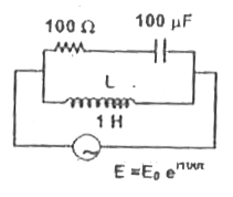
QFind the impedance of AC circuit at resonance shown in the adjacent figure
![Consider the parallel resonant circuit shown in adjacent figure. One branch contains an inductor of inductance L and a small ohmic resistance R, whereas the other branch contains a capacitor of capacitance C. The circuit is fed by a source of alternating emfE= E(o) e^(jomegat)=E(o) sin omegat The impedance of inductor branch, Z (1)= R + jomegaL The impendence of capacitor branch, Z(2) = (1//jomegaC) therefour Net impedance Z of the two parallel branches is given by (1)/(Z)=(1)/(Z(1))+ (1)/)Z(2)=(1)/(R+jomegaC =(R-jomegaL)/(jomegaL)(R-jomegaL)+jomegaC=(R)/(R^(2)+omega^(2)+L^(2))+jomega[C-(L)/(R^(2)+omegaL^(2))] The current flowing in the circuit I=(E)/(Z)=(E)[(R)/(R^(2)+omega^(2)L^(2))+jomega(C-(L)/(R^(2)+omega^(2)L^(2)))] For resonance to occur, the current must be in phase with the applied emf. For this, the reactive component of current should be zero, l.e. omega[C-(L)/(R^(2)+omega^(2)L^(2))]=0 orC=(L)/(R^(2)+omega(r)^(2)L^(2))(writing omega(r)for omegaat resonance) This gives resonant angular frequency omega(r)=sqrt((1)/(LC)-R^(2)/(L^(2))) At parallel circuit resonance, theimpendence is maximum and current is minimum. Parallel resonant circuit is sometimes called the anti-resonance in order to distinguish from series resonance QFind the impedance of AC circuit at resonance shown in the adjacent figure Find the impedance of AC circuit at resonance shown in the adjacent figure](https://d10lpgp6xz60nq.cloudfront.net/physics_images/FIITJEE_PHY_MB_06_C03_E04_001_Q01.png)
Find the impedance of AC circuit at resonance shown in the adjacent figure
100√2Ω
200Ω
100Ω
200√2√
The correct Answer is:A
Topper's Solved these Questions
- BOOK - FIITJEECHAPTER - AC CIRCUITSEXERCISE - COMPREHENSION-(II)( Assuming that any resistance of inductor is included in R, answer the following question)10videos
AC CIRCUITS
- BOOK - FIITJEECHAPTER - AC CIRCUITSEXERCISE - ASSERTION REASONING TYPE1videos
AC CIRCUITS
- BOOK - FIITJEECHAPTER - AC CIRCUITSEXERCISE - ASSIGNMENT PROBLEMS(OBJECTIVELevel - Il)14videos
AC CIRCUITS
- BOOK - FIITJEECHAPTER - COLLISION EXERCISE - (NUMERICAL BASED QUESTIONS)4videos
COLLISION
Similar Questions
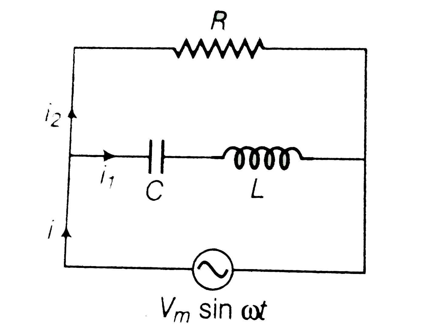
Consider the L-C-R circuit shown in the fiure. Find the net current I and the phase of i. Show that i=VZ. Find the impedance Z of this circuit.
 View Solution
Consider the L-C-R circuit shown in the fiure. Find the net current I and the phase of i. Show that i=VZ. Find the impedance Z of this circuit.
 View Solution
Knowledge Check
- Question 1 - Select One
Consider the parallel resonant circuit shown in adjacent figure. One branch contains an inductor of inductance L and a small ohmic resistance R, whereas the other branch contains a capacitor of capacitance C. The circuit is fed by a source of alternating emfE=Eoejωt=Eosinωt
The impedance of inductor branch, Z(1)=R+jωL
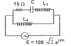
The impendence of capacitor branch, Z(2) = (1//jomegaC)therefourNetimpedanceZofthetwoparal≤lbranchesisgivenby<br>(1)/(Z)=(1)/(Z_(1))+ (1)/)Z_(2)=(1)/(R+jomegaC<br>=(R-jomegaL)/(jomegaL)(R-jomegaL)+jomegaC=(R)/(R^(2)+omega^(2)+L^(2))+jomega[C-(L)/(R^(2)+omegaL^(2))]<br>Thecurrentflow∈g∈the∘uit<br>I=(E)/(Z)=(E)[(R)/(R^(2)+omega^(2)L^(2))+jomega(C-(L)/(R^(2)+omega^(2)L^(2)))]<br>Forresonance→our,thecurrentμstbe∈phasewiththeappliedemf.Forthis,thereactivecompo≠ntofcurrentshod––bezero,l.e.<br>omega[C-(L)/(R^(2)+omega^(2)L^(2))]=0<br>orC=(L)/(R^(2)+omega_(r)^(2)L^(2))(writ∈gomega_(r)foromegaatresonance)<br>Thisgivesresonantanga––requency<br>omega_(r)=sqrt((1)/(LC)-R^(2)/(L^(2)))Atparal≤l∘uitresonance,theimpendenceismaxiμmandcurrentisminiμm.Paral≤lresonant∘uitissome×cal≤dtheanti−resonance∈order→dist∈guishomseriesresonance<br>QF∈dtheimpedanceofAC∘uitatresonanceshown∈theadjacentfigure<br><imga≤ocr_imageload∈g=lazysrc=https://d10lpgp6xz60nq.cloudfront.net/physics_images/FIITJEE_PHY_MB_06_C03_E04_002_Q01.pngwh=80%mx-autosty≤=background:white;><br>Thereactanceofthe∘uit∈theadjacentfigureis20Ω.F∈dthevalueofI_(rms)
 A4 AmpB2 AmpC4.5 AmpD13.5 Amp
 - Question 2 - Select One
Consider the parallel resonant circuit shown in adjacent figure. One branch contains an inductor of inductance L and a small ohmic resistance R, whereas the other branch contains a capacitor of capacitance C. The circuit is fed by a source of alternating emfE=Eoejωt=Eosinωt
The impedance of inductor branch, Z(1)=R+jωL
The impendence of capacitor branch, Z(2) = (1//jomegaC)therefourNetimpedanceZofthetwoparal≤lbranchesisgivenby<br>(1)/(Z)=(1)/(Z_(1))+ (1)/)Z_(2)=(1)/(R+jomegaC<br>=(R-jomegaL)/(jomegaL)(R-jomegaL)+jomegaC=(R)/(R^(2)+omega^(2)+L^(2))+jomega[C-(L)/(R^(2)+omegaL^(2))]<br>Thecurrentflow∈g∈the∘uit<br>I=(E)/(Z)=(E)[(R)/(R^(2)+omega^(2)L^(2))+jomega(C-(L)/(R^(2)+omega^(2)L^(2)))]<br>Forresonance→our,thecurrentμstbe∈phasewiththeappliedemf.Forthis,thereactivecompo≠ntofcurrentshod––bezero,l.e.<br>omega[C-(L)/(R^(2)+omega^(2)L^(2))]=0<br>orC=(L)/(R^(2)+omega_(r)^(2)L^(2))(writ∈gomega_(r)foromegaatresonance)<br>Thisgivesresonantanga––requency<br>omega_(r)=sqrt((1)/(LC)-R^(2)/(L^(2))) At parallel circuit resonance, theimpendence is maximum and current is minimum. Parallel resonant circuit is sometimes called the anti-resonance in order to distinguish from series resonance
QFind the impedance of AC circuit at resonance shown in the adjacent figure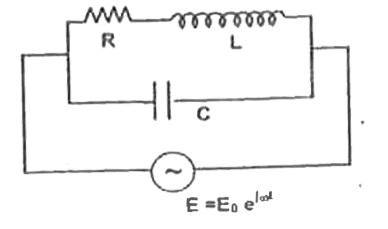
A coil of inductance 100 muH and 60 Omega effective resistance is connected in parallel with a condenser of 100 pF. The resonant circuit so formed is excited from an alternating current source. The frequency of the source is varied until the maximum impendence of the circuit is obtained. The frequency of the generator at which this occurs is approximatelyA(1022πHzB(1072πHzC(1052πHZD(1032πHz - Question 3 - Select One
Consider the parallel resonant circuit shown in adjacent figure. One branch contains an inductor of inductance L and a small ohmic resistance R, whereas the other branch contains a capacitor of capacitance C. The circuit is fed by a source of alternating emfE=Eoejωt=Eosinωt
The impedance of inductor branch, Z(1)=R+jωL
The impendence of capacitor branch, Z(2) = (1//jomegaC)therefourNetimpedanceZofthetwoparal≤lbranchesisgivenby<br>(1)/(Z)=(1)/(Z_(1))+ (1)/)Z_(2)=(1)/(R+jomegaC<br>=(R-jomegaL)/(jomegaL)(R-jomegaL)+jomegaC=(R)/(R^(2)+omega^(2)+L^(2))+jomega[C-(L)/(R^(2)+omegaL^(2))]<br>Thecurrentflow∈g∈the∘uit<br>I=(E)/(Z)=(E)[(R)/(R^(2)+omega^(2)L^(2))+jomega(C-(L)/(R^(2)+omega^(2)L^(2)))]<br>Forresonance→our,thecurrentμstbe∈phasewiththeappliedemf.Forthis,thereactivecompo≠ntofcurrentshod––bezero,l.e.<br>omega[C-(L)/(R^(2)+omega^(2)L^(2))]=0<br>orC=(L)/(R^(2)+omega_(r)^(2)L^(2))(writ∈gomega_(r)foromegaatresonance)<br>Thisgivesresonantanga––requency<br>omega_(r)=sqrt((1)/(LC)-R^(2)/(L^(2)))Atparal≤l∘uitresonance,theimpendenceismaxiμmandcurrentisminiμm.Paral≤lresonant∘uitissome×cal≤dtheanti−resonance∈order→dist∈guishomseriesresonance<br>QF∈dtheimpedanceofAC∘uitatresonanceshown∈theadjacentfigure<br><imga≤ocr_imageload∈g=lazysrc=https://d10lpgp6xz60nq.cloudfront.net/physics_images/FIITJEE_PHY_MB_06_C03_E04_003_Q01.pngwh=80%mx-autosty≤=background:white;><br>Foranac∘uit,impendenceisgivenbyZ = 50 + jK(P^(2) - 4Q^(2), where K is a positive non-. zero constant. For resonance, which of the following expression is trueAP =2 QBP =QCP+Q=KDP-Q=K
Consider the parallel resonant circuit shown in adjacent figure. One branch contains an inductor of inductance L and a small ohmic resistance R, whereas the other branch contains a capacitor of capacitance C. The circuit is fed by a source of alternating emfE=Eoejωt=Eosinωt
The impedance of inductor branch, Z(1)=R+jωL
The impendence of capacitor branch, Z(2) = (1//jomegaC)therefourNetimpedanceZofthetwoparal≤lbranchesisgivenby<br>(1)/(Z)=(1)/(Z_(1))+ (1)/)Z_(2)=(1)/(R+jomegaC<br>=(R-jomegaL)/(jomegaL)(R-jomegaL)+jomegaC=(R)/(R^(2)+omega^(2)+L^(2))+jomega[C-(L)/(R^(2)+omegaL^(2))]<br>Thecurrentflow∈g∈the∘uit<br>I=(E)/(Z)=(E)[(R)/(R^(2)+omega^(2)L^(2))+jomega(C-(L)/(R^(2)+omega^(2)L^(2)))]<br>Forresonance→our,thecurrentμstbe∈phasewiththeappliedemf.Forthis,thereactivecompo≠ntofcurrentshod––bezero,l.e.<br>omega[C-(L)/(R^(2)+omega^(2)L^(2))]=0<br>orC=(L)/(R^(2)+omega_(r)^(2)L^(2))(writ∈gomega_(r)foromegaatresonance)<br>Thisgivesresonantanga––requency<br>omega_(r)=sqrt((1)/(LC)-R^(2)/(L^(2))) At parallel circuit resonance, theimpendence is maximum and current is minimum. Parallel resonant circuit is sometimes called the anti-resonance in order to distinguish from series resonance
QFind the impedance of AC circuit at resonance shown in the adjacent figure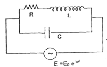
Which of the following graph shows correct relation beteen current I and frequency f in a parallel AC circuitView SolutionAn L-C_R series circuit is joined to a source of alternating e.m.f. If R=9Ω,XL=28Ω,XC=16Ω, then the impedance of the circuit will be
View SolutionThe current flowing in two branches of parallel resonant circuit at resonance are
View SolutionThe value of impedance in parallel LC circuit at resonance is (assuming inductor and capacitor to be ideal)
View SolutionThe impedance of a circuit, when a resistance R and an inductor of inductance are connected in series in an AC circuit of frequency f is
View Solution
