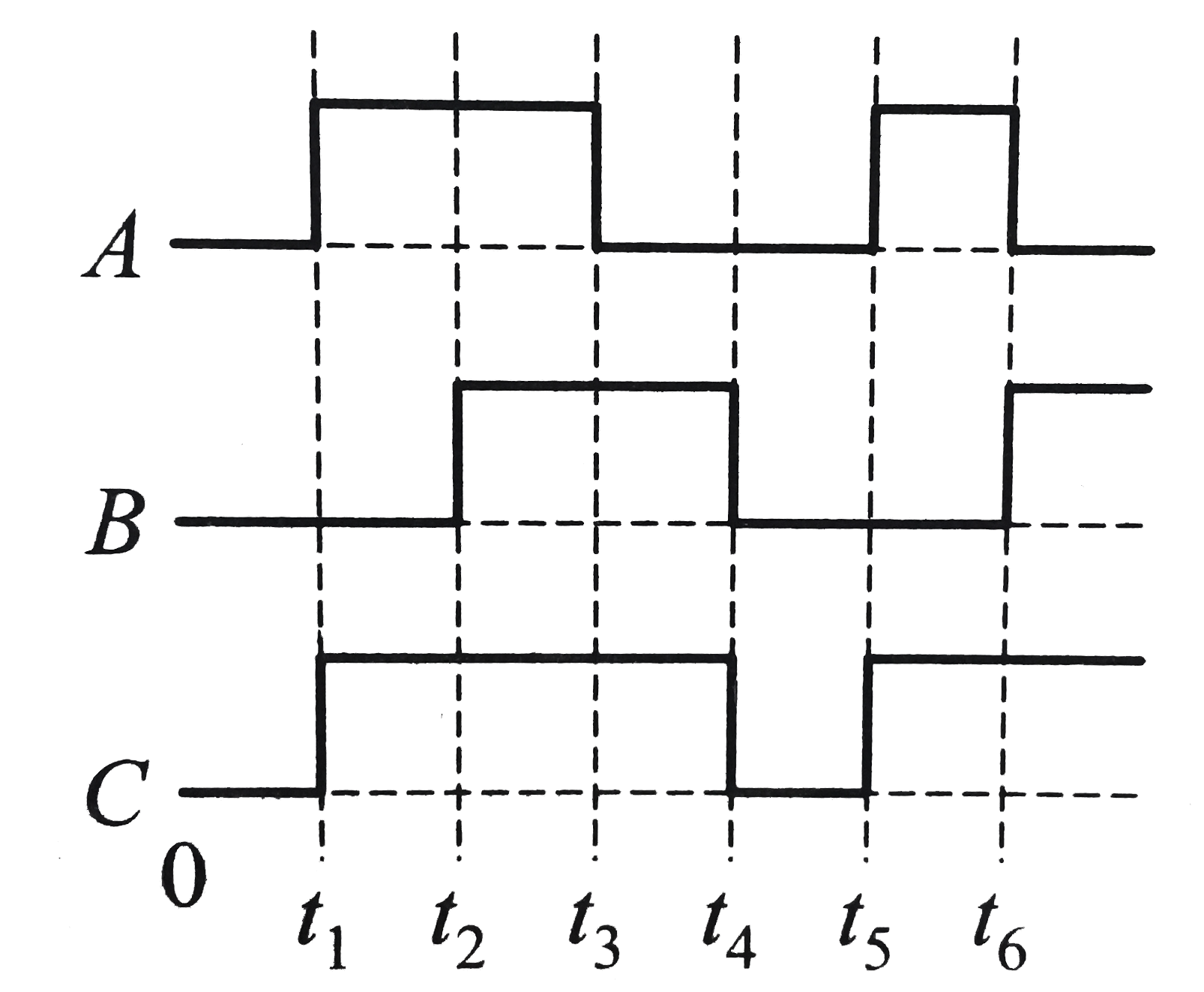
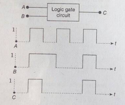
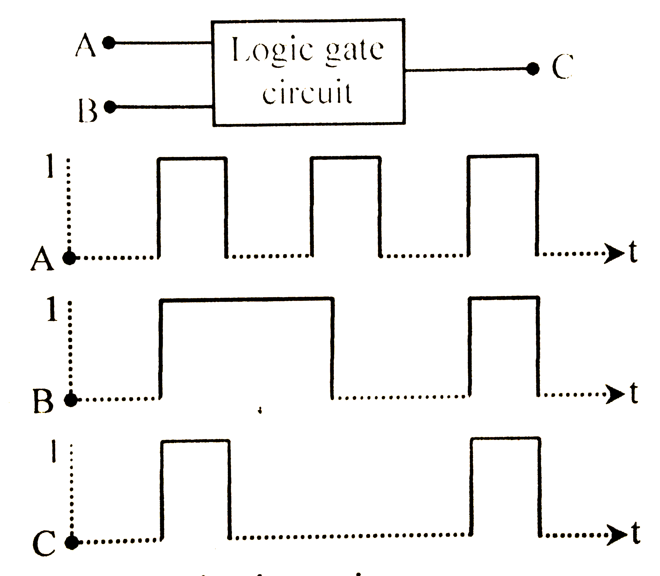
The figure shows a logic circuit with two inputs A and B and the output C. The voltage wave forms across A,B and C are as given. The logic circuit gate is
NAND gate
OR gate
NOR gate
AND gate
The correct Answer is:B
From the given waveforms, the following truth table can be obtained
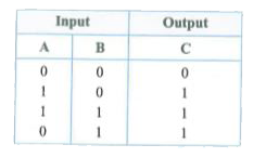
This truth table corresponds to .OR. gate. So, logic circuit gate is OR gate.
Topper's Solved these Questions
- SEMICONDUCTOR ELECTRONICSBOOK - NARAYNACHAPTER - SEMICONDUCTOR ELECTRONICSEXERCISE - EXERCISE-4
35 Videos
- SEMICONDUCTOR ELECTRONICSBOOK - NARAYNACHAPTER - SEMICONDUCTOR ELECTRONICSEXERCISE - ADDITIONAL EXERCISE (ASSERTION AND REASON TYPE QUESTIONS :)
19 Videos
- SEMICONDUCTOR ELECTRONICSBOOK - NARAYNACHAPTER - SEMICONDUCTOR ELECTRONICSEXERCISE - EXERCISE -2 (H.W) (LOGIC GATE)
6 Videos
- SEMI CONDUCTOR DEVICESBOOK - NARAYNACHAPTER - SEMI CONDUCTOR DEVICESEXERCISE - Level-II (H.W)
36 Videos
- WAVE OPTICSBOOK - NARAYNACHAPTER - WAVE OPTICSEXERCISE - Exercise - 4 Polarisation
9 Videos
Similar Questions
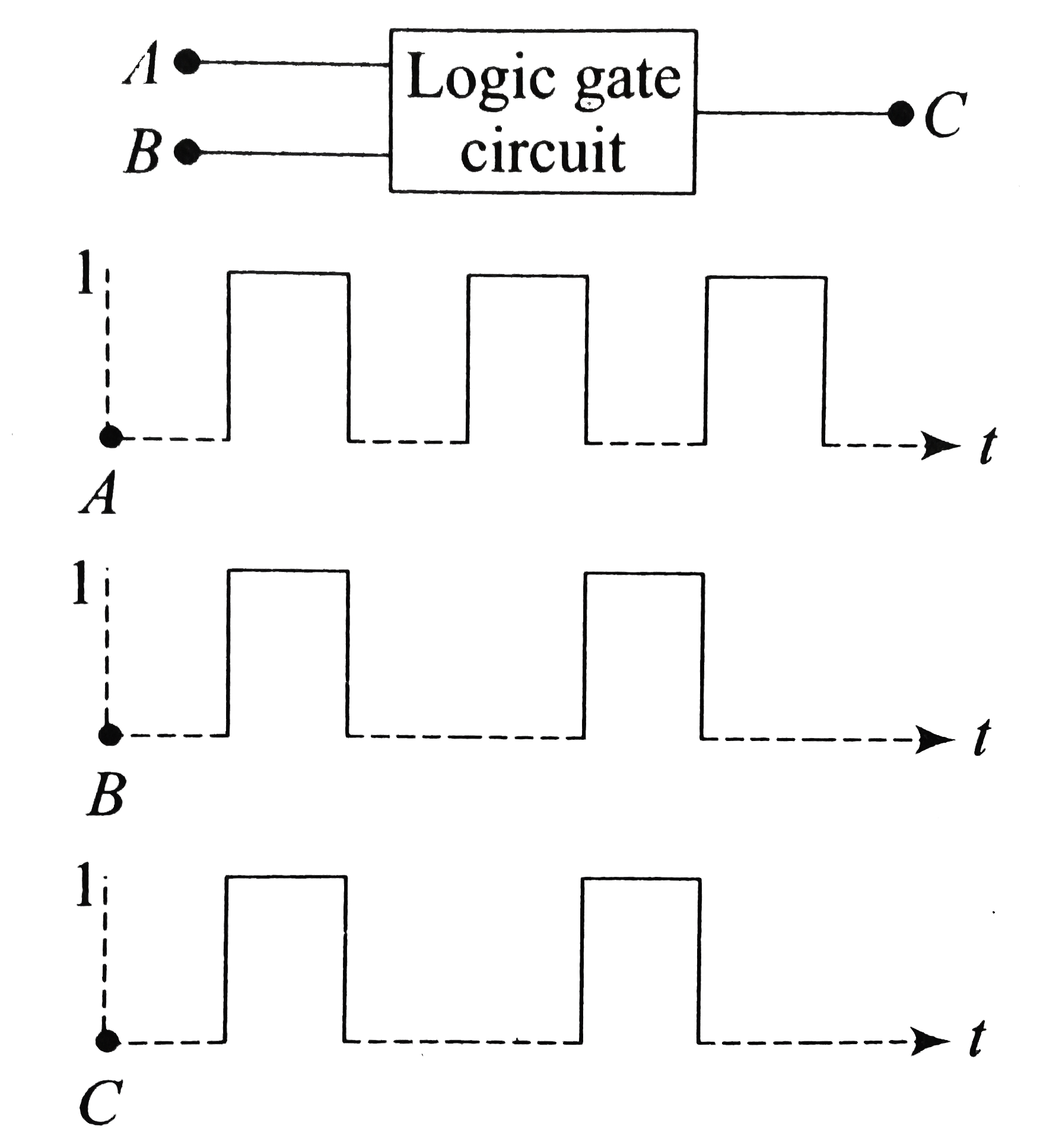
The following figure shows a logic gate circuit with two inputs A and B and the output C. The voltage waveforms of A, B and C are as shown below.
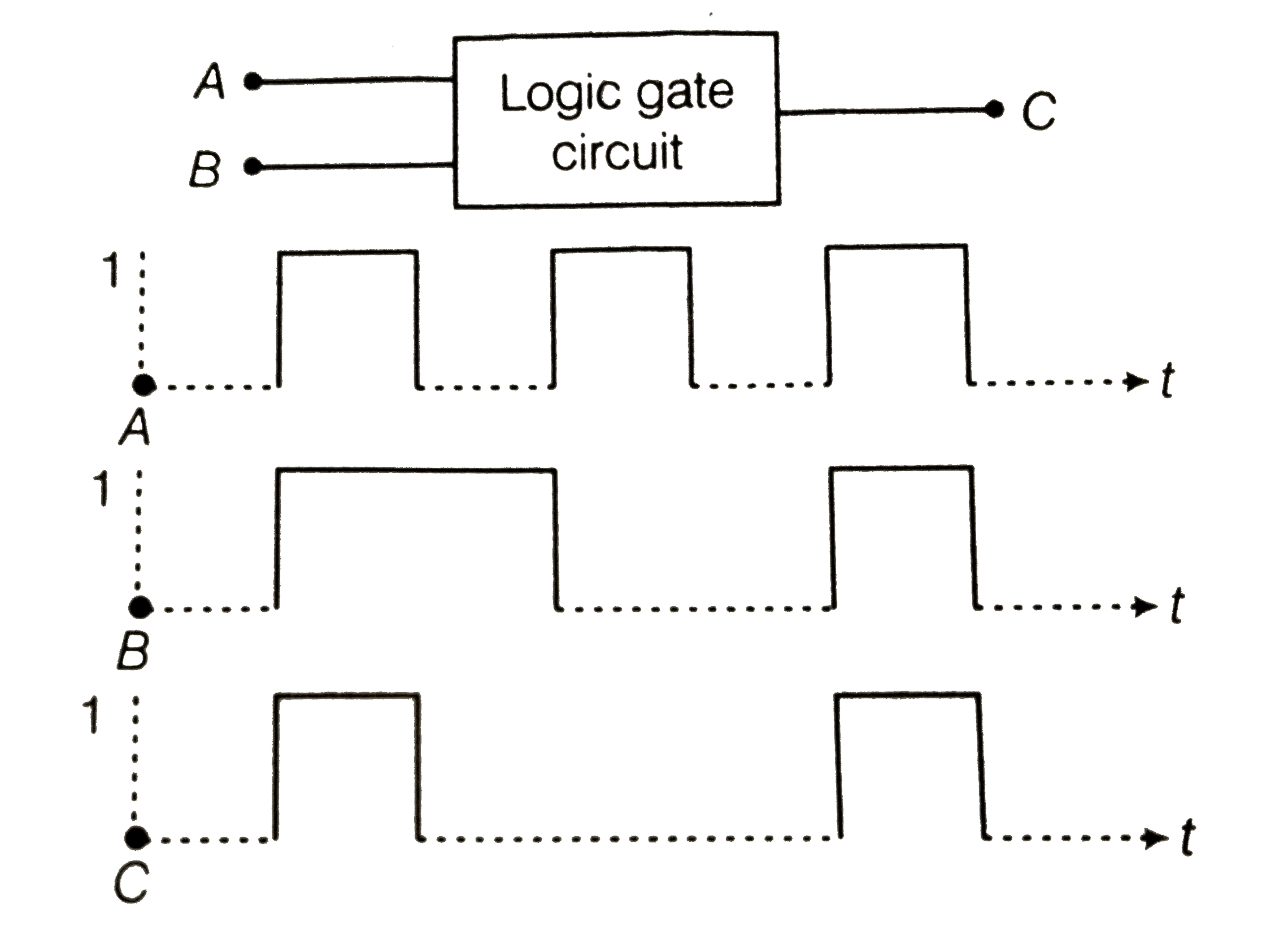
The logic circuit gate is
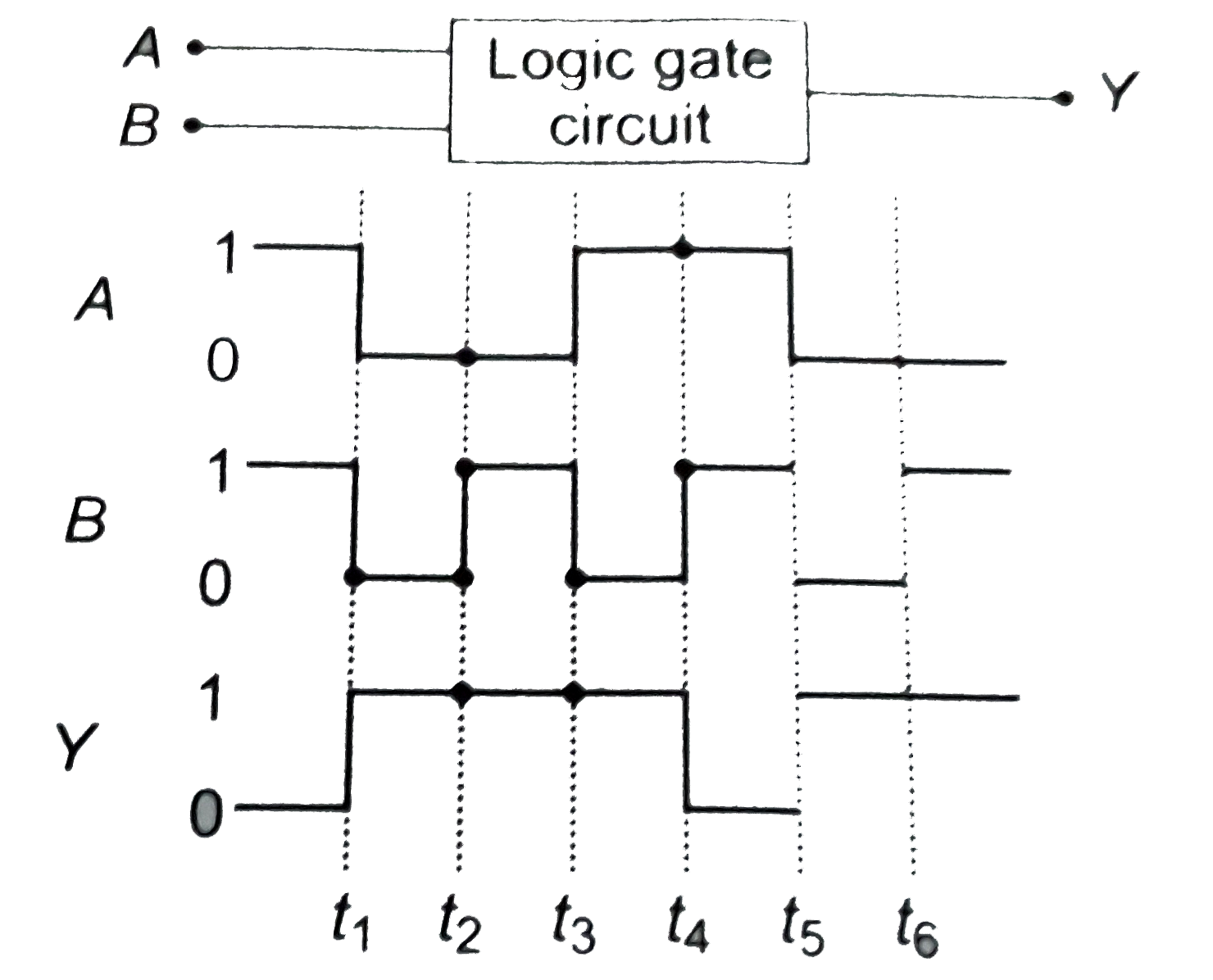
View SolutionThe following figure shows a logic gate circuit with two inputs A and B and the output Y. The voltage waveforms of A,B and the output Y are as given
View Solution
Knowledge Check
The following figure shows a logic gate circuit with two inputs A and B and the output C. The voltage waveforms of A, B and C are as shown below
The logic circuit gate isAAND gateBNAND gateCNOR gateDOR gateThe following figure shows a logic gate circuit with two inputs A and B and the output C. The voltage waveforms of A, B and C are as shown below

The logic circuit gate isAAND gateBNAND gateCNOR gateDOR gateThe following shows a logic gate circuit with two inputs A and B and the output C. The voltage waveforms of A, B and C are as shown below.
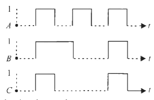
The logic circuit gate isAOR gateBAND gateCNAND gateDNOR gate
The following figure shows a logic gate circuit with two inputs A and B and the output Y. The voltage waveforms of A,B and Y are as given :
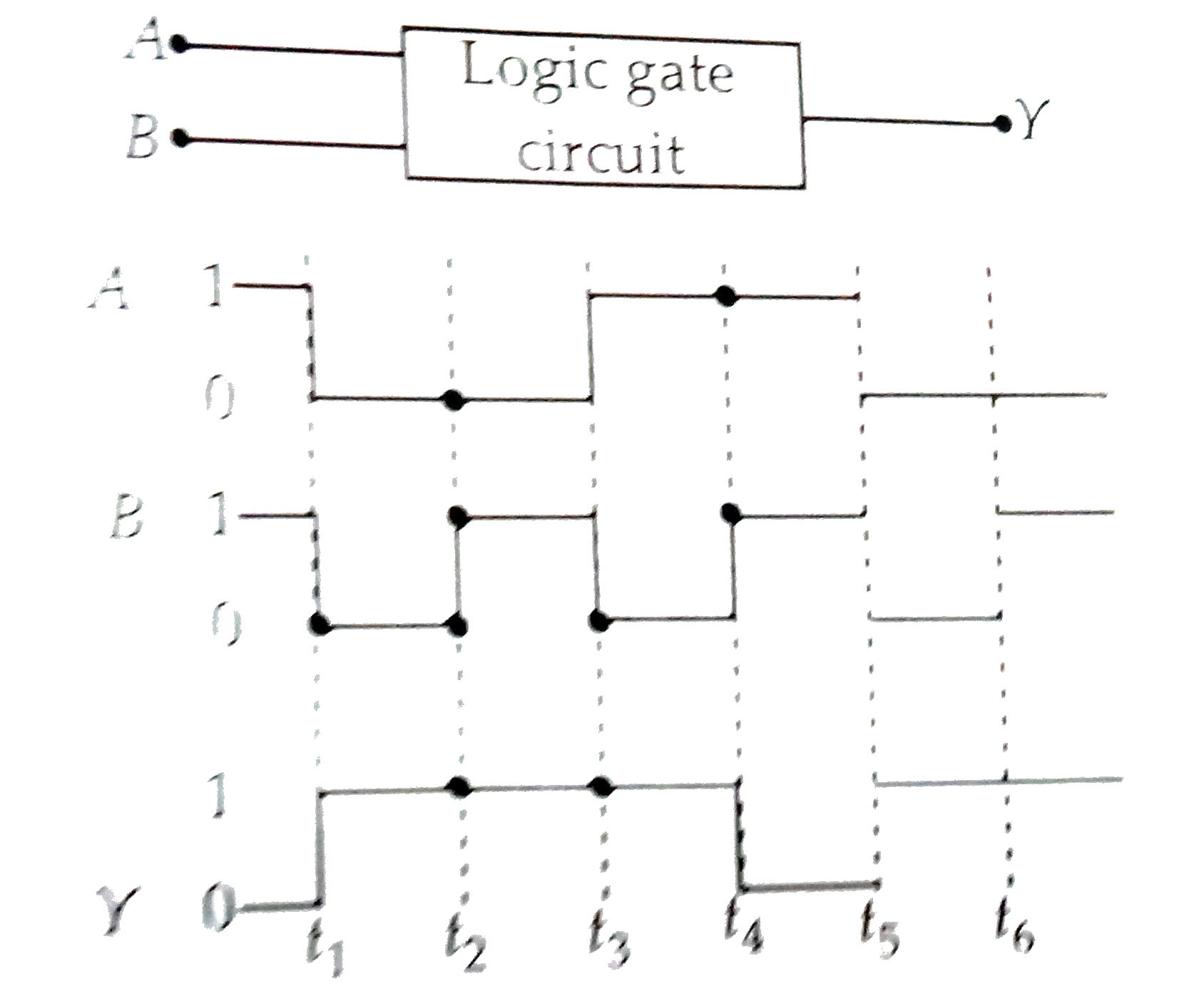
The logic gate is
View SolutionFig, shows a logic gate circuit with two input A and B and the output C. The voltage wave form of A, B and C are as shown in Fig.The logic gate circuit is
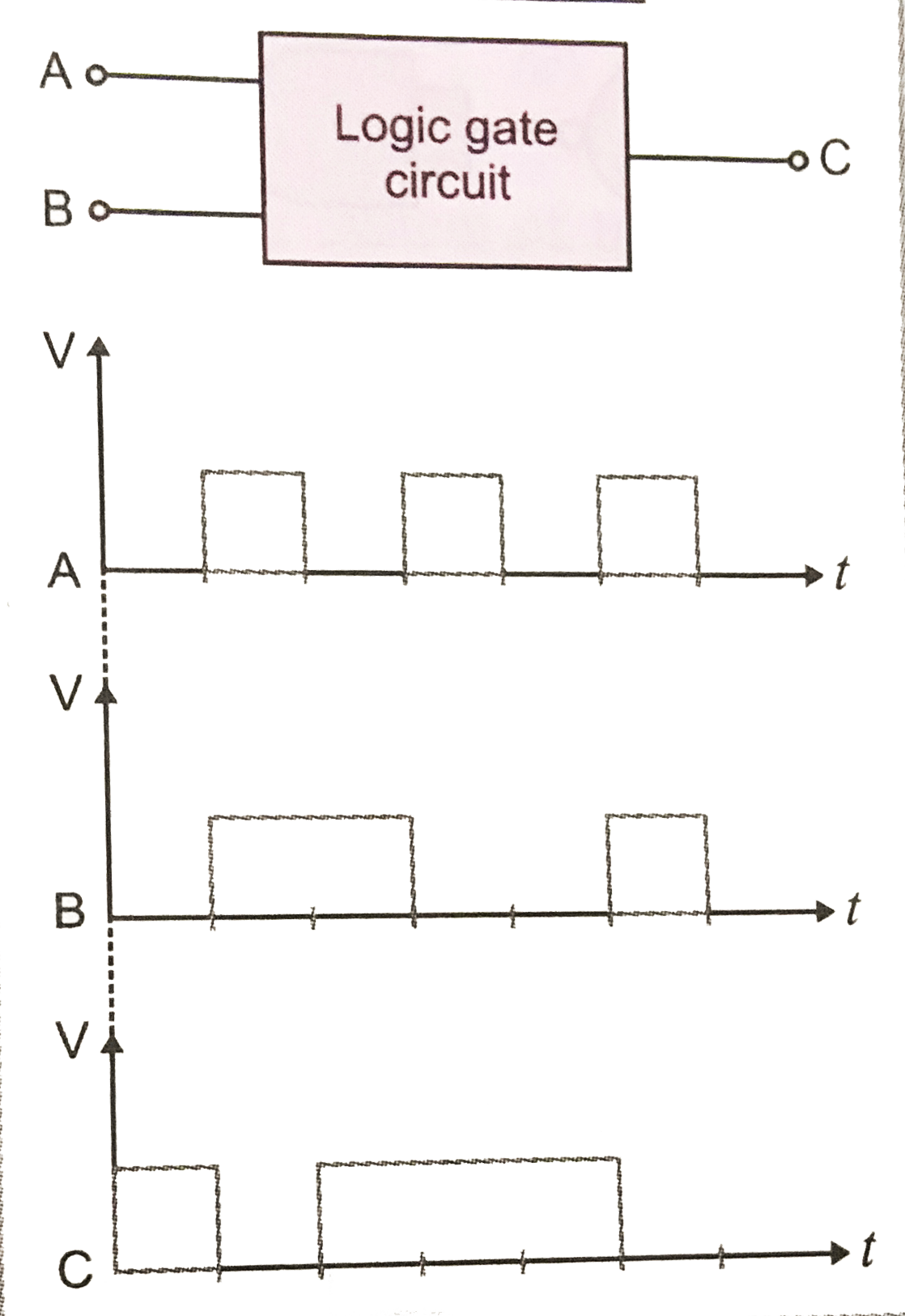
View SolutionThe following figure shows a logic gate circuit with two inputs A and B and the output C. The voltage waveforms of A, B and C are as shown below-
View SolutionThe following figure shows a logic gate circuit with two inputs A and B and the output C. The voltage waveforms of A,B and C are as shown below
View SolutionThe following figure shows a logic gate circuit with two inputs A and B and the output Y. The voltage waveforms of A,B and the output Y are as given

View Solution
