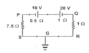
In the circuit shown
A
the potential at
B
the potential at
C
the potential at R is zero
D
the potential al S is zero
Video Solution
Text Solution
The current in the circuit
The potential difference across PS,
The potential difference across Q, R,
As point G is connected to earth, hence potentials of R and Sare zero. The direction of the current in the circuit is from P to S, hence point P is at higher potential
therefore,
Similarly,
Hence, (B) (C) & (D) are correct.
|
Updated on:21/07/2023
Topper's Solved these Questions
- BOOK - FIITJEECHAPTER - CURRENT ELECTRICITYEXERCISE - Exercise9videos
CURRENT ELECTRICITY
- BOOK - FIITJEECHAPTER - CURRENT ELECTRICITYEXERCISE - Comprehension Based Type-13videos
CURRENT ELECTRICITY
- BOOK - FIITJEECHAPTER - CURRENT ELECTRICITYEXERCISE - SOLVED PROBLEMS (SUBJECTIVE)10videos
CURRENT ELECTRICITY
- BOOK - FIITJEECHAPTER - COLLISION EXERCISE - (NUMERICAL BASED QUESTIONS)4videos
COLLISION
- BOOK - FIITJEECHAPTER - ELASTICITY AND WAVES EXERCISE - Assignment Problems (Objective) Level-II15videos
ELASTICITY AND WAVES
Similar Questions
Knowledge Check
- Question 1 - Select One or More
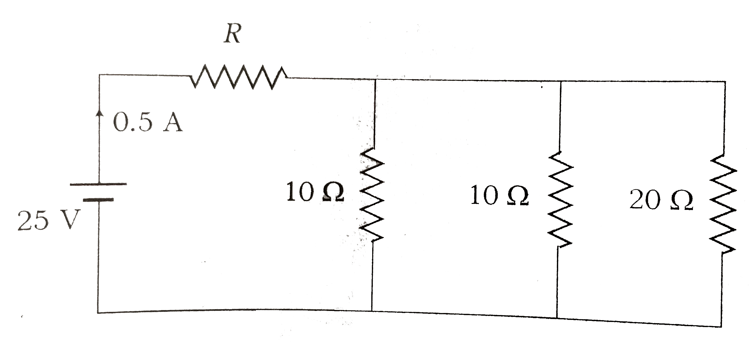
For the circuit shown in the following figure.
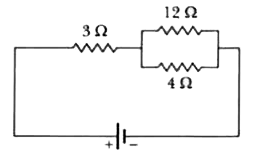 AThe heat dissipated in 4Ω resistance is more than that dissipated in 12Ω resistanceBMaximum heat is dissipated in 3Ω resistanceCThe heat dissipated in 12Ω resistance is more than that dissipated in 4Ω resistanceDThe power dissipated in 3Ω resistance is 18 W
 - Question 2 - Select One
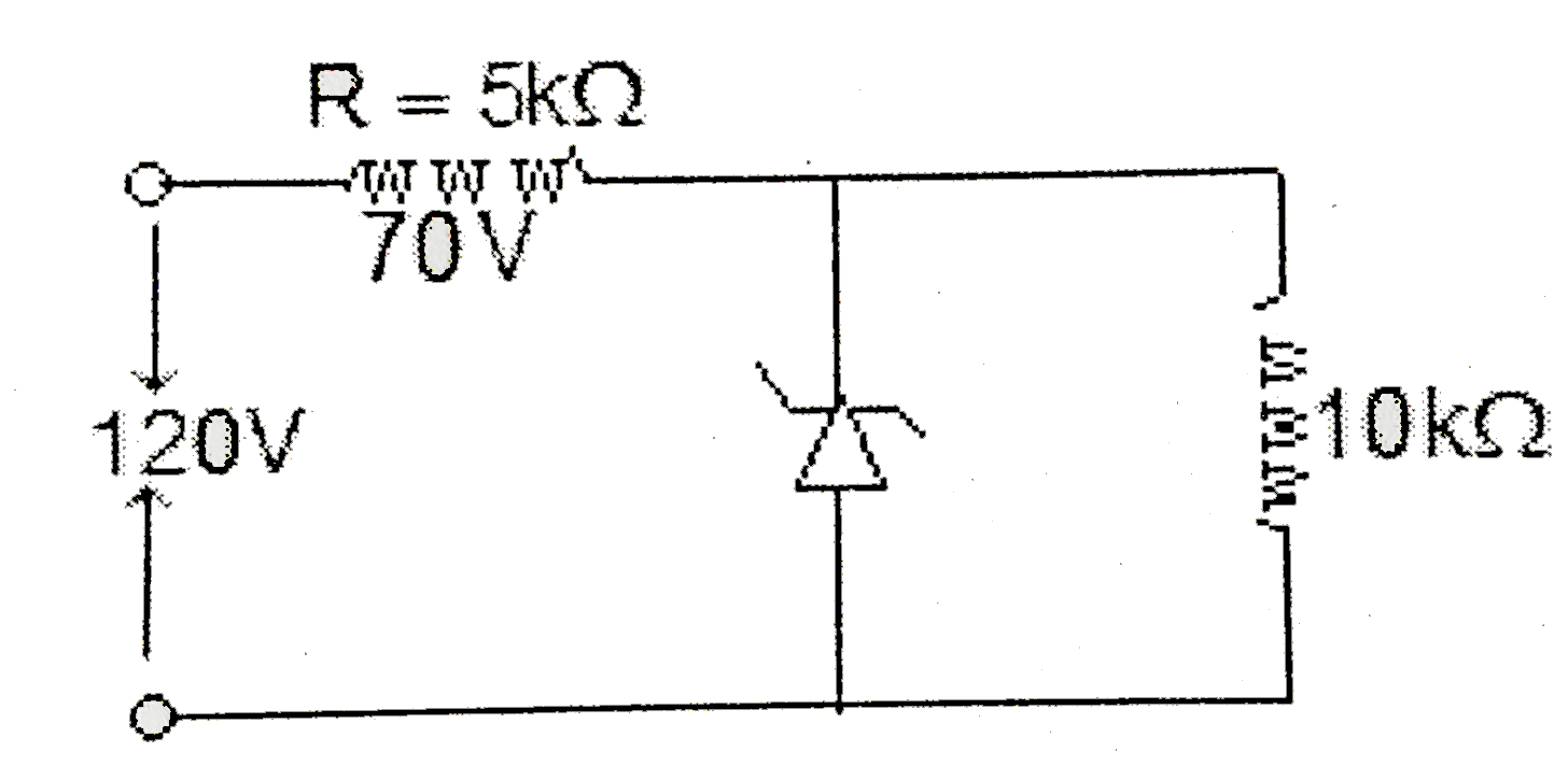
For the circuit shown in the figure :
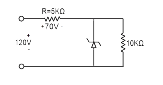 ACurrent through Zener diode is 4 mABCurrent through Zener diode is 9 mACThe output voltage is 60 VDThe output voltage is 40 V
 - Question 3 - Select One or More
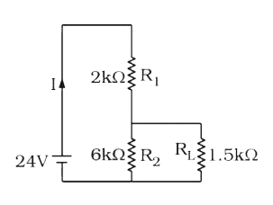
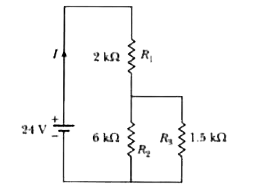
For the circuit shown in figure
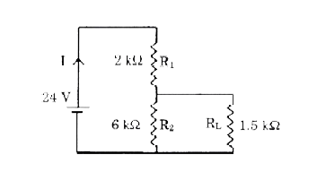
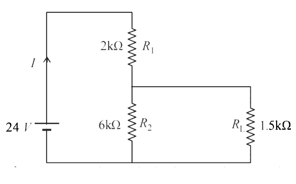 Athe current I through the batter is 7.5 mA.Bthe potential difference across R_L is 18V.Cratio of powers dissipated in R1andR2 is 3Dif R1andR2 are interchanged, magnitude of the power dissipated in RL will decrease by a factor of 9.

