Draw circuit diagram for a full wave rectifier and show input output voltages.
Rectification. Rectification is the process of converting alternating voltage/current into direct voltage/current. A device used for this purpose is called rectifier and this phenomenon is called rectification.
Principle. It is based on the principle that a p-n junction diode conducts when it is forward biased and does not conduct when it is reverse biased.
Construction. The apparatus for rectification consists of two diodes D1 and D2 connected to two ends of the secondary of a step down transformer. Output is taken out from mid point of the secondary and common point N of two diodes. Ouput is taken out from ends of the load R.

Working. During the positive half of input AC,D1 is forward biased and D2 reverse biased. Hence the current flows through the upper circuit as shown. During negative half, lower portion (D2) is forward biased and upper (D1) is reverse biased.
Thus during each half, we get the current either from D1 or from D2.
The output voltage is unidirectional having ripple contents.
Ripple factor of a rectifier =r.m.s of a.c.componentvalue of d.c. component
To smoothen the output electric filters are used. The electric filters are combination of inductors are capacitors. Some of the useful filters are L-filter and π-filter.
Topper's Solved these Questions
- SOLIDS AND SEMICONDUCTOR DEVICESBook:MBD -HARYANA BOARDChapter:SOLIDS AND SEMICONDUCTOR DEVICESExercise:Long answer type questions
Explore 6 Videos
- SOLIDS AND SEMICONDUCTOR DEVICESBook:MBD -HARYANA BOARDChapter:SOLIDS AND SEMICONDUCTOR DEVICESExercise:Objective type questions
Explore 21 Videos
- SOLIDS AND SEMICONDUCTOR DEVICESBook:MBD -HARYANA BOARDChapter:SOLIDS AND SEMICONDUCTOR DEVICESExercise:Objective type questions
Explore 21 Videos
- PRINCIPLES OF COMMUNICATIONBook:MBD -HARYANA BOARDChapter:PRINCIPLES OF COMMUNICATIONExercise:Objective Type Questions
Explore 19 Videos
Similar Questions
Knowledge Check
The output form of full-wave rectifier is
AAn AC voltageBA DC voltageCZeroDA pulsating unidirectional voltage
Draw a circuit diagram of a full-wave rectifier. Explain its working principle. Draw the input/output wave forms indicating clearly the function of the two diode used.
View SolutionWhat is a rectifier ? Draw circuit diagram for a rectifier in which ouput is obtained continuously.
View SolutionDraw a neat labelled circuit diagram of full wave rectifier using semiconductor diode.
View SolutionDraw a circuit diagram of a full-wave rectifier. Explain its working principle. Draw the input/output wave forms indicating clearly the function of the two diode used.
View SolutionDraw the circuit diagram of a half wave rectifier. Hence explain its working.
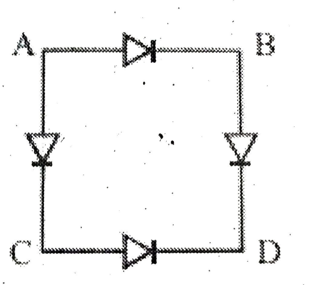
View SolutionGiven cicuit work as a full wave rectifier then input and output terminals will be respectively

View SolutionThe rms value of input voltage in a full wave rectifier is 12 V determine the output voltage if a step up a transformer with ratio 1:2 is used
View Solution