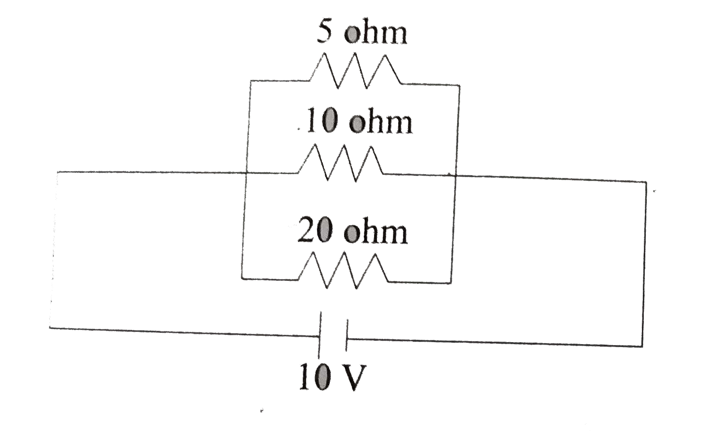
In the circuit diagram given below, three resistors R1,R2 and R3 of 5Ω,10Ω and 20Ω respectively are cooncted as shown.
(A) Current through each resistor
(B) Total current in the circuit
(c ) Total resistance in the circuit
 Solution in Tamil
Since the resistors are connected in parallel, the potential difference across each resistor is same (i.e. V=10V)
Therefore, the current through R1 is
I1=VR1=105=2A
Current through R2=I2=VR2=1010=1A
Current through R3=I3=VR1020=0.5A
(B) Total current in the circuit, I=I1+I2+I3
=2+1+0.5=3.5A
(C) Total resistance in the circuit 1Rp=1R1+1R2+1R3
=15+110+120
=4+2+120
1Rp=720
Hence, Rp=207=2.857Ω
Topper's Solved these Questions
- ELECTRICITYBOOK - FULL MARKSCHAPTER - ELECTRICITYEXERCISE - Textual Evaluation (I. Choose the best answer)
4 Videos
- ELECTRICITYBOOK - FULL MARKSCHAPTER - ELECTRICITYEXERCISE - Textual Evaluation (II. Fill in the blanks )
5 Videos
- DEPARTMENTAL MODEL PAPER (SOLVED)BOOK - FULL MARKSCHAPTER - DEPARTMENTAL MODEL PAPER (SOLVED)EXERCISE - PART-IV
6 Videos
- LAWS OF MOTIONBOOK - FULL MARKSCHAPTER - LAWS OF MOTIONEXERCISE - Additional Questions (VIII. Problems.)
2 Videos
Similar Questions
Which of the following is correct ?
View SolutionFill in the blanks:
(i) The amount of work done to move charge from one point to another is called_____.
(ii) When a circuit is open,_____ cannot pass through it.
View SolutionExplain the experiment of measuring the real and apparent expansion of a liquid with a neat diagram.
View SolutionA cricket ball of mass 0.5 kg strikes a bat normally with a velocity of 30 ms−1 and rebounds with a velocity of 20 ms−1 in the opposite direction, calculate the impulse of the force exerted by the ball on the bat.
View SolutionIn the circuit diagram given in (Fig. 3.57), calculate : (a) the current through each resistor (b) the total current in the circuit ( c) the total effective resistance of the circuit. .
View SolutionIf in Fig. 12.12, R_(1)=10Omega, R_(2)=40Omega, R_(3)=30Omega, R_(5)=60Omega, and a 12 V battery is connected to the arrangemtn. Calculate (a) the total resistance in the circuit, and (b) the total current flowing in the circuit.
View SolutionThe circuit diagram given below shows the combination of three resistors R_(1),R_(2) and R_(3) : Find: (i) total resistance of the circuit. (ii) total current flowing in the circuit. (iii) the potential difference across R_(1) .
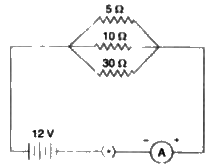
View SolutionIn the circuit diagram given below, three resistors R1,R2, and R3 of 5Ω,10Ω and 30Ω, respectively are connected as shown.
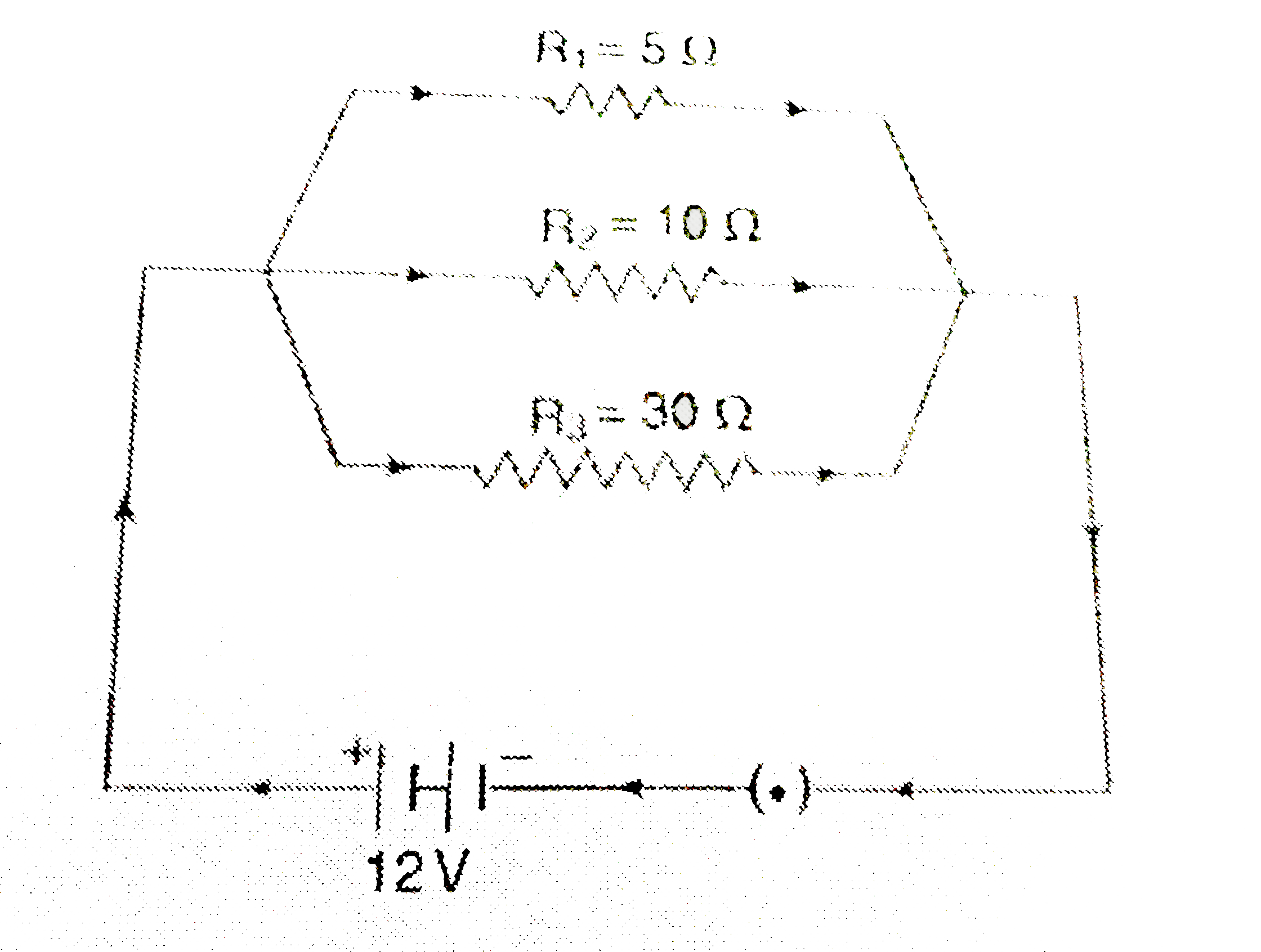
Calculate:
(a) current through each resistor.
(b) total current in the circuit.
(c) total resistance in the circuit.
View SolutionIn the given circuit, calculate - (a) the total resistance of the circuit, (b) the current through the circuit, and (c) the potential differences across R_(1) and R_(2)
View Solutionनिम्न परिपथ आरेख में , ज्ञात कीजिए :
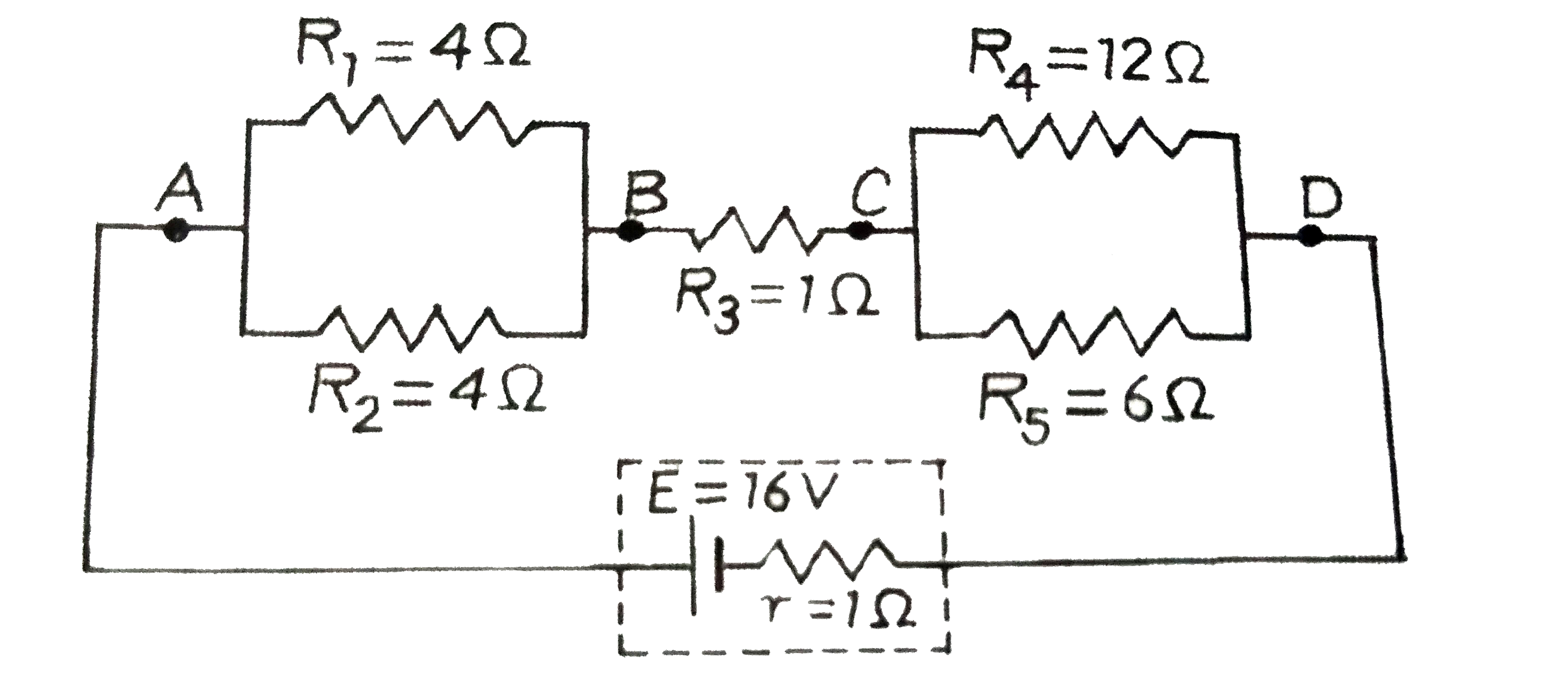
परिपथ का तुल्य - प्रतिरोध तथा R3,R4 प्रतिरोधों में प्रवाहित धाराएँ ।
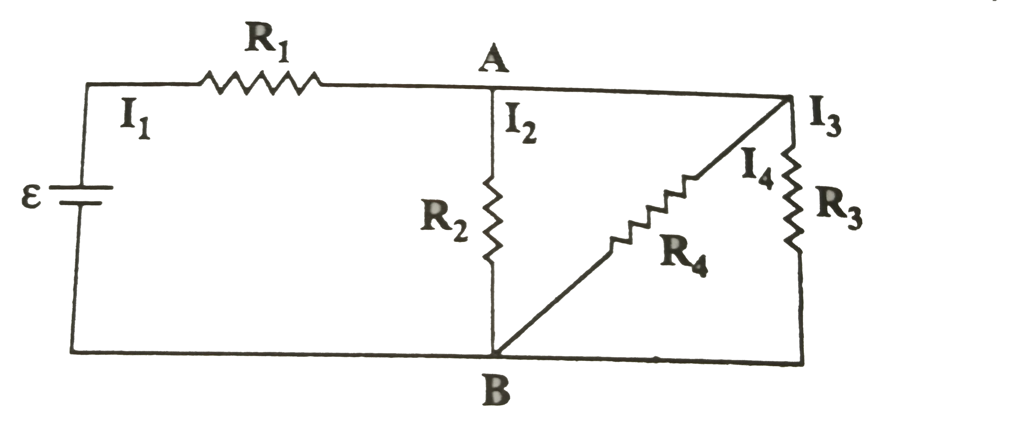
View Solutionदर्शाए गए परिपथ में R1=4Ω,R2=R3=5Ω,R4=10Ω तथा ε=6V परिपथ का तुल्य प्रतिरोध तथा प्रत्येक प्रतिरोधक में बहने वाली धारा के मान परिकलित कीजिए।
View SolutionIn circuit diagram R_(1), R_(2) And R_(3) Three resistors whose values are respectively 5Omega, 10Omega And 15Omega With a 12 volt battery, then calculate - (a) Total current flowing in the circuit. (b) the total resistance of the circuit.
View SolutionIn the circuit diagram given below, three resistors R1,R2, and R3 of 5Ω,10Ω and 30Ω, respectively are connected as shown.

Calculate:
(a) current through each resistor.
(b) total current in the circuit.
(c) total resistance in the circuit.
View SolutionIf in Fig. 12.12, R1=10Ω,R2=40Ω,R3=30Ω,R5=60Ω, and a 12 V battery is connected to the arrangemtn. Calculate (a) the total resistance in the circuit, and (b) the total current flowing in the circuit.
View SolutionIn the given circuit diagram, calculate :
(a) the value of current through each resistor
(b) the total current in the circuit
(c) the total effective resistance of the circuit.
View Solution
