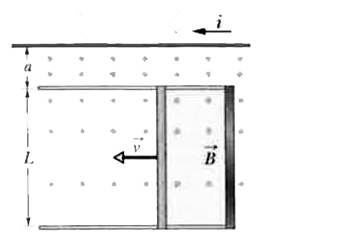
Figure 30-50 shows a rod of length L = 12.0 cm that is forced to move at constant speed v = 5.00 m/s along horizontal rails. The rod, rails, and connecting strip at the right form a conducting loop. The rod has resistance 0.400 Ω the rest of the loop has negligible resistance. A current i = 100 A through the long straight wire at distance a= 5.00 mm from the loop sets up a (nonuniform) magnetic field through the loop. Find the (a) emf and (b) current induced in the loop. (c) At what rate is thermal energy generated in the rod? (d) What is the magnitude of the force that must be applied to the rod to make it move at constant speed? (e) At what rate does this force do work on the rod?
(a) 322 μV, (b) 0.805 mA, (c) 0.259 μW, (d) 51.8 nN, (e) 0.259 μW
Topper's Solved these Questions
- ELECTROMAGNETIC INDUCTIONBOOK - RESNICK AND HALLIDAYCHAPTER - ELECTROMAGNETIC INDUCTIONEXERCISE - PRACTICE QUESTIONS (Single Correct Choice Type)
45 Videos
- ELECTROMAGNETIC INDUCTIONBOOK - RESNICK AND HALLIDAYCHAPTER - ELECTROMAGNETIC INDUCTIONEXERCISE - PRACTICE QUESTIONS (More than One Correct Choice Type)
13 Videos
- ELECTROMAGNETIC INDUCTIONBOOK - RESNICK AND HALLIDAYCHAPTER - ELECTROMAGNETIC INDUCTIONEXERCISE - CHECKPOINTS
9 Videos
- ELECTRIC POTENTIALBOOK - RESNICK AND HALLIDAYCHAPTER - ELECTRIC POTENTIALEXERCISE - (PRACTICE QUESTIONS) Integer Type
1 Videos
- ELECTROMAGNETIC OSCILLATIONS AND ALTERNATING CURRENT BOOK - RESNICK AND HALLIDAYCHAPTER - ELECTROMAGNETIC OSCILLATIONS AND ALTERNATING CURRENT EXERCISE - Practice Questions (Integer)
7 Videos
Similar Questions
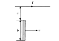
A rod of length b moves with a constant velocity v in the magnetic field of a straight long conductor that carries a current I as shown in the below figure. The emf induced in the rod is
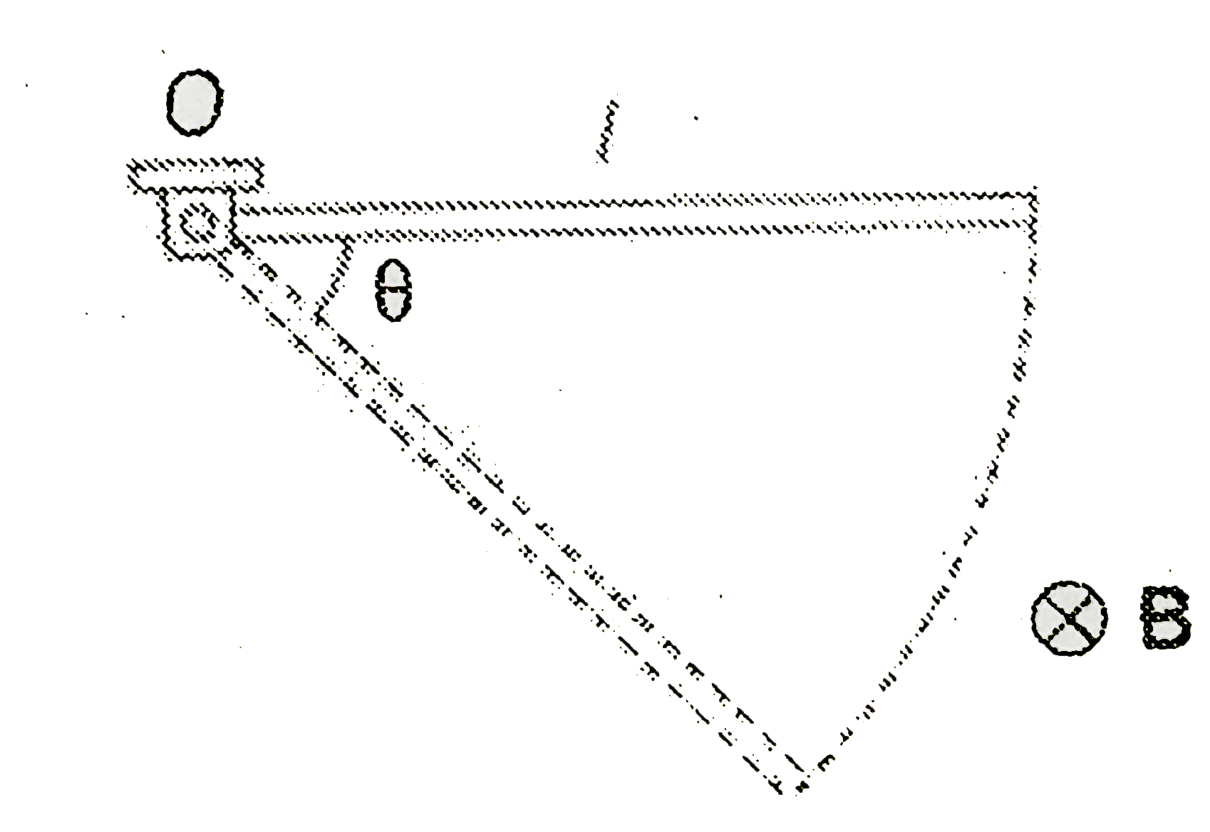
View SolutionA conducting rod of length l is hinged at point O. It is a free to rotate in a verical plane. There exists a uniform magnetic field B in horizontal direction. The rod is released from the position shown. The potential difference between the two ends of the rod is proportional to
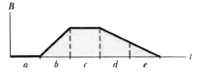
View SolutionThe graph gives the magnitude B(t) of a uniform magnetic field that exists throughout a conducting loop, with the direction of the field perpendicular to the plane of the loop. Rank the five regions of the graph according to the magnitude of the emf induced in the loop, greatest first.
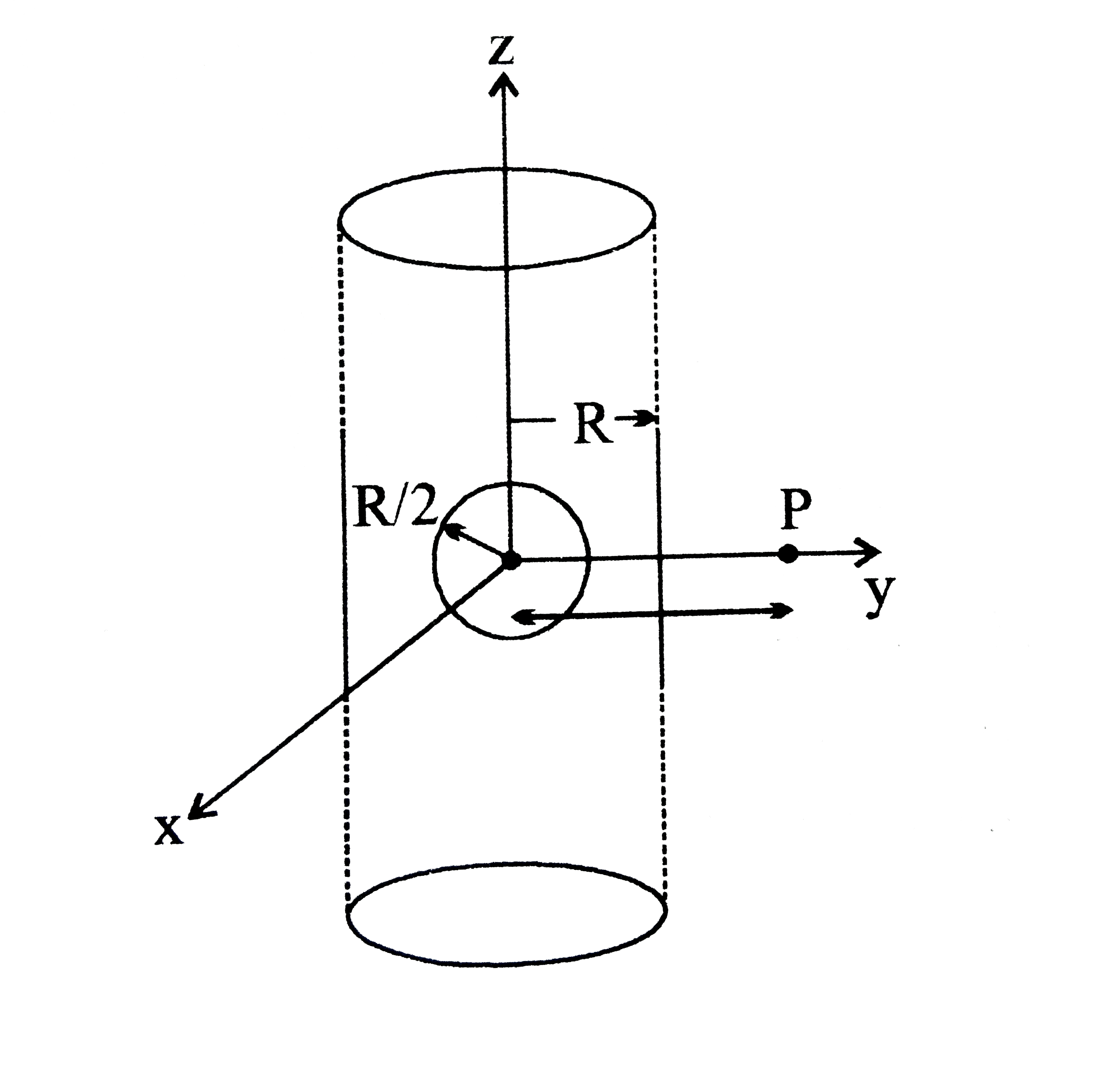
View SolutionAn infinitely long solid cylinder of radius R has a uniform volume charge density ρ. It has a spherical cavity of radius R/2 with its centre on the axis of cylinder, as shown in the figure. The magnitude of the electric field at the point P, which is at a distance 2R form the axis of the cylinder, is given by the expression 23rR16ke0 . The value of k is .
 .
.
View SolutionAn a.c source of frequency 1000Hz is connected to a coil of 200πmH and negligible resistance. If effective current through the coil is 7.5mA, what is the voltage (in volt) across the coil ?
View SolutionFigure shows a conducting rod of negligible resistance that can slide on smooth U-shaped rail made of wire of resistance 1Omega//m . Position of the conducting rod at t=0 is shown. A time dependent magnetic field B=2t tesla is switched on at t=0 The current in the loop at t=0 due to induced emf is
View SolutionA conducting circular loop of radius a and resistance per unit length R is moving with a constant velocity v_0 , parallel to an infinite conducting wire carrying current i_0 . A conducting rod of length 2a is approaching the centre of the loop with a constant velocity v_0/2 along the direction 2 of the current. At the instant t = 0 , the rod comes in contact with the loop at A and starts sliding on the loop with the constant velocity. Neglecting the resistance of the rod and the self-inductance of the circuit, find the following when the rod slides on the loop. (a) The current through the rod when it is at a distance of (a/2) from the point A of the loop. (b) Force required to maintain the velocity of the rod at that instant.
View SolutionTwo long parallel conducting rails are placed in a uniform magnetic field. On one side, the rails are connected with a resistance R . Two rods MN and M'N' each having resistance r are placed as showing in Fig. Now on the rods MN and M'N' forces are applied such that the rods move with constant velocity v . (i). The current flowing through resistance R if the rod Mn moves toward left and the rod M'N' moves toward the right is
View SolutionIn Fig. shown, the rod has a resistance R , the horizontal rails have negligible friction. A battery of emf E and negligible internal resistance is connected between points a and b . The rod is released from rest. The current when the rod attains its terminal speed is
View SolutionFigure shows a conducting rod of negligible resistance that can slide on smooth U- shaped rail made of wire of resistance 1Omega//m . Position of the conducting rod at t=0 is shown. A time t dependent magnetic filed B=2t Tesla is switeched on t=0 At t=0 , when the magnetic field to switched on, the conducting rod is moved to the left at constant speed 5cm//s by some external means. The rod moves perpendicular to the rails. At t=2s , induced emf has magnitude.
View SolutionTwo parallel fixed conducting rails are l distance apart. They are connected by a conducting wire xy. A uniform magnetic field B is applied normal to its plane. Two other rods PQ and RT(RS = ST) are moved with a constant velocity v. Resistance/ length of these two rods are lamda no other wire has resistance. Then :
View SolutionA pair of long conducting rails are held vertical at a separation l = 50 cm . The top ends are connected by a resistance of R = 0.5 Omega and a fuse (F) of negligible resistance. A conducting rod is free to slide along the rails under gravity. The whole system is in a uniform horizontal magnetic field B = 1.5 T as shown. Resistance of the rod and rails are negligible and the rod remains horizontal as it moves. The rod is released from rest. Find the minimum mass of the rod that will ensure that the fuse blows out. It is known that rating of the fuse is 4 A.
View SolutionIn Fig. 30-37, a metal rod is forced to move with constant velocity vecv along two parallel metal rails, connected with a strip of metal at one end. A magnetic field of magnitude B = 0.125 T points out of the page. ( a) If the rails are separated by L = 25.0 cm and the speed of the rod is 38.0 emfs, what emf is generated? (b) If the rod has a resistance of 18.0 Omega and the rails and connector have negligible resistance, what is the current in the rod? (c) At what rate is energy being transferred to thermal energy? (d) What is the magnitude of the leftward force that causes the rod to move?
View SolutionThe conducting rod shown in Fig. 30-37 has length Land is being pulled along horizontal, frictionless conducting rails at a constant velocity vecv . The rails are connected at one end with a metal strip. A uniform magnetic field vecB , directed out of the page, fills the region in which the rod moves. Assume that L = 10 cm, v = 5.0 m/s, and B = 1.2 T. What are the (a) magnitude and (b) direction (up or down the page) of the emf induced in the rod? What are the (c) size and (d) direction of the current in the conducting loop? Assume that the resistance of the rod is 0.40 Omega and that the resistance of the rails and metal strip is negligibly small. (e) At what rate is thermal energy being generated in the rod? (f) What external force on the rod is needed to maintain vecv ? (g) At what rate does this force do work on the rod?
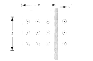
View SolutionA rod with resistance R lies across frictionless conducting rails in a constant uniform magnetic field →B, as shown in the following figure. Assume the rails have negligible resistance. The magnitude of the force that must be applied by a person to pull the rod to the right at constant speed v is
View Solution
