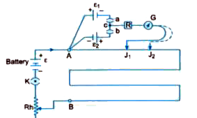
A student uses the circuit diagram of a potentiometer as shown in Fig.

(a) For a steady current I passing through the potentiometer wire, he gets a null point for the cell ε1and not for ε2 . Give reason for this observation and suggest how this difficulty can be resolved.
(b) What is the function of resistance R used in the circuit? How will the change in its value affect the null point ?
(c ) How can the sensitivity of the potentiometer be increased?
(a) The student does not get a null point for the cell ε2 because cell ε2 is connected in the circuit wrongly. The difficulty can be resolved by connecting + ve terminal of ε2 to point A and - ve terminal to key .b..
(b) The resistance R reduces the current passing through the galvanometer when the jockey contact is far away from the null point. As a result, the galvanometer is protected from the damage likely to be caused by a strong current. A change in value of resistance R does not affect the null point.
(c) Sensitivity of the potentiometer can be increased by lowering the value of potential gradient along the potentiometer wire. It can be achieved (i) by increasing the total length of potentiometer, (ii) by placing a resistance in the auxiliary circuit of driver cell in series of the potentiometer.
Topper's Solved these Questions
- CURRENT ELECTRICITY Book:U-LIKE SERIESChapter:CURRENT ELECTRICITY Exercise:LONG ANSWER QUESTIONS - II
Explore 8 Videos
- CURRENT ELECTRICITY Book:U-LIKE SERIESChapter:CURRENT ELECTRICITY Exercise:SELF ASSESSMENT TEST (SECTION A (MULTIPLE CHOICE QUESTIONS))
Explore 6 Videos
- CURRENT ELECTRICITY Book:U-LIKE SERIESChapter:CURRENT ELECTRICITY Exercise:SHORT ANSWER QUESTIONS
Explore 42 Videos
- CBSE SAMPLE QUESTION PAPER 2019-20 (SOLVED)Book:U-LIKE SERIESChapter:CBSE SAMPLE QUESTION PAPER 2019-20 (SOLVED)Exercise:SECTION D
Explore 6 Videos
- DUAL NATURE OF RADIATION AND MATTERBook:U-LIKE SERIESChapter:DUAL NATURE OF RADIATION AND MATTERExercise:SELF ASSESSMENT TEST SECTION-C (VERY SHORT ANSWER QUESTIONS)
Explore 3 Videos
Similar Questions
When a balance point is obtained in a potentiometer for finding the internal resistance of a cell, the current through the potentiometer wire is due to
View SolutionState the principle of potentiometer. Draw a circuit diagram used to compare the emfs of two primary cells. Write the formula used. How can the sensitivity of a potentiometer be increased.
View Solution
Knowledge Check
As is the cross sectional area and ρ is the specific resistance of a potentiometer wire. If I is the current passing through the potentiometer wire, then the potential gradient along the length of the wire is given by
AIAρBIAρCIρADIρAThe potentiometer wire of resistance R is connected in series with a cell of e.m.f. E and of resistance Rh. The current flowing through the potentiometer wire is
AI=ER+r+RhBI=ER+rCI=RERh+rDI=ERAssertion: Potentiometer measures correct value of emf of a cell.
Reason: No current flows through cell at null point of potentiometer.AIf both Assertion & Reason are True & the Reason is a correct explanantion of the AssertionBIf both Assertion & Reason True but Reason is not a correct explanation of the AssertionCIf Assertion is True but the Reason is FalseDIf both Assertion & Reason are False.
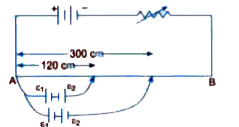
In the Fig., a long uniform potentiometer wire AB is having a constant potential gradient along its length. The null points for the two primary cells of emf ε1 and ε2 connected in the manner shown are obtained at a distance of 120 cm and 300 cm from the end A. Find (i)ε1/ε2 and (ii) position of null point for the cell ε1. How is the sensitivity of a potentiometer increased ?

View SolutionAssertion: Potentiometer measures correct value of emf of a cell.
Reason: No current flows through cell at null point of potentiometer.
View SolutionDraw a circuit diagram for the determination of the internal resistance of a cell using potentiometer. Derive the formula to be used.
View SolutionWrite the principle of working of a potentiometer. Describe briefly, with the help of a circuit diagram, how a potentiometer is used to determine the internal resistance of a cell.
View SolutionIf the potentiometer wire having resistance ρ ohm/ m and I amp. current is allowed to pass through it. The potential gradient produced on the potentiometer wire will be
View Solution
