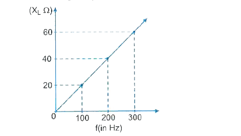
The variation of inductive reactance (XL) of an inductor with the frequency (f) of the a.c. source of 100 V and variable frequency is shown in the figure.

(i) Calculate the self-inductance of the inductor.
(ii) When this inductor is used in series with a capacitor of unknown value and a resistor of 10Ω at 300 s−1, maximum power dissipation occurs in the circuit. Calculate the capacitance of the capacitor.
(i) As per XL -f graph for a frequency f = 100 Hz , XL=20Ω
∴XL=Lω=L.2πf
⇒L=XL2πf=202×3.14×100=0.032Hor32 mH
(ii) As at a frequency f0=300s−1 maximum power dissipation occurs the frequecny f0 is the resonant frequency .
We know that f0=12π√LC,soC=14π2f20L⇒C=14×(3.14)2×(300)2×0.032=8.85F
Topper's Solved these Questions
- CBSE EXAMINATION PAPER 2020 (SOLVED)BOOK - U-LIKE SERIESCHAPTER - CBSE EXAMINATION PAPER 2020 (SOLVED)EXERCISE - SECTION C
11 Videos
- CBSE EXAMINATION PAPER 2020 BOOK - U-LIKE SERIESCHAPTER - CBSE EXAMINATION PAPER 2020 EXERCISE - SECTION D
12 Videos
- CBSE EXAMINATION PAPER 2020 (SOLVED) BOOK - U-LIKE SERIESCHAPTER - CBSE EXAMINATION PAPER 2020 (SOLVED) EXERCISE - SECTION - D
6 Videos
Similar Questions
A resistor, a capacitor of 100μF capacitance and an inductor are in series with on AC source of frequency 50Hz. If the current in the circuit is in phase with the applied voltage. The inductance of the inductor is
View SolutionOne 2 ohm resistor is connected in series with an inductor of reactance 1Ω to a 5 V (rms ) A C source . Find the average power dissipated in the circuit .
View Solution
Knowledge Check
An inductance L , a capacitor of 20μF and a resistor of 10Ω are connected in series with an AC source of frequency 50 Hz . If the current is in phase with the voltage, then the inductance of the inductor is
A2.00 HB0.51 HC1.5 HD0.99 HAn inductor of reactance 1 Ω and a resistor of 2 Ω are connected in series to the terminals of a 6 V (rms) a.c. source. The power dissipated in the circuit is
A8 WB12 WC14.4 WD18 W
An inductance L , a capacitor of 20μF and a resistor of 10Ω are connected in series with an AC source of frequency 50 Hz . If the current is in phase with the voltage, then the inductance of the inductor is
View SolutionA resistor 10Ω, a capacitor of 100μF capacitance and an inductor are in series with on AC source of frequency 50Hz. If the current in the circuit is in phase with the applied voltage. The inductance of the inductor is
View SolutionA capacitor of 100μF, a resistor of 20Ω and an inductor of inductance L are connected in series with an a.c. source of frequency 50 Hz. Calculate the value of inductance L of the inductor, if phase angle between current and voltage is zero.
View SolutionAn inductor of unknown value, a capacitor of 100 uF and a resistor of 10 Ω are connected in series to a 200 V, 50 Hz a.c. source. It is found that the power factor of the circuit is unity. Calculate the inductance of the inductor and the current amplitude.
View SolutionAn inductor of unknown value, a capacitor of 100μF and a resistor of 10 ohm are conneted in series to a 200 V, 50 Hz a.c. source It is found that power factor of the circuit is unity. Calculate inductance of the inductor and current amplitude.
View SolutionA inductor of reactance 1Ω and a resistor of 2Ω are connected in series to the terminals of a 6 V (rms) a.c. source. The power dissipated in the circuit is
View Solution
