Figure 27-56 shows the circuit of a flashing lamp, like those attached to barrels at highway construction sites. The fluorescent lamp L (of negligible capacitance) is connected in parallel, across the capacitor C of can RC circuit. There is a current through the lamp only when it potential difference across it reaches the breakdown voltage VL, then the capacitor discharges completely through the lamp and the lamp flashes briefly. For a lamp with breakdown voltage VL=75.0V, wired to a 95.0 V ideal battery and a 0.150μF capacitor, what resistance R is needed for two flashes per second?
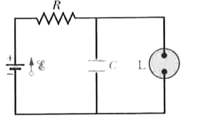
The correct Answer is:2.14×10⁶Ω
Topper's Solved these Questions
- CIRCUITSBOOK - RESNICK AND HALLIDAYCHAPTER - CIRCUITSEXERCISE - Practice Questions (Single Correct Choice Type)
33 Videos
- CIRCUITSBOOK - RESNICK AND HALLIDAYCHAPTER - CIRCUITSEXERCISE - Practice Questions (More than One Correct Choice Type)
12 Videos
- CIRCUITSBOOK - RESNICK AND HALLIDAYCHAPTER - CIRCUITSEXERCISE - Checkpoints
7 Videos
- CENTER OF MASS BOOK - RESNICK AND HALLIDAYCHAPTER - CENTER OF MASS EXERCISE - Practice Questions (Integer )
4 Videos
- CIRCULAR MOTIONBOOK - RESNICK AND HALLIDAYCHAPTER - CIRCULAR MOTIONEXERCISE - CHECK POINTS
6 Videos
Similar Questions
Figure shows the circuit of a flashing lamp, used at construction sites. The fluorescent lamp L, having negligible capacitance, is connected in parallel across the capacitor C of an RC circuit . There is a current through the lamp only when the potential difference across it reaches the breakdown voltage V1). In this event, the capacitor discharges completley through the lamp and lamp flashes momentarily.
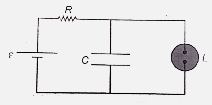
Which of the following graphs represents the variation fo potential drop across the resistor ?
View SolutionFigure shows the circuit of a flashing lamp, used at construction sites. The fluorescent lamp L, having negligible capacitance, is connected in parallel across the capacitor C of an RC circuit . There is a current through the lamp only when the potential difference across it reaches the breakdown voltage V1). In this event, the capacitor discharges completley through the lamp and lamp flashes momentarily.
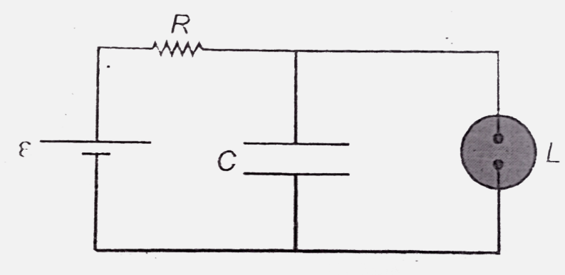
The number of flashes per second produced by the arrangement is ( neglecting th etime of flashing or discharging of capacitor)
View Solution
Knowledge Check
The purpose of choke in a fluorescent lamp is ,
Ato increase the current flowBto decrease the current flowCto decrease the resistenceDro decrease the voltage momentarilyIn the circuit shown in the figure, if both the lamps L1 and L2 are identical
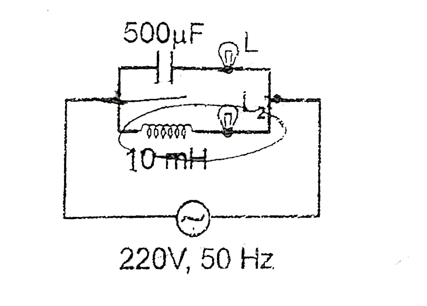 ATheir brightness will be sameBL2 will be brighter than L1CAs frequency of supply voltage is increased brightness of L1 will increase and that of L2 will decreaseDOnly L2 will glow because the capacitor has infinite resistance.
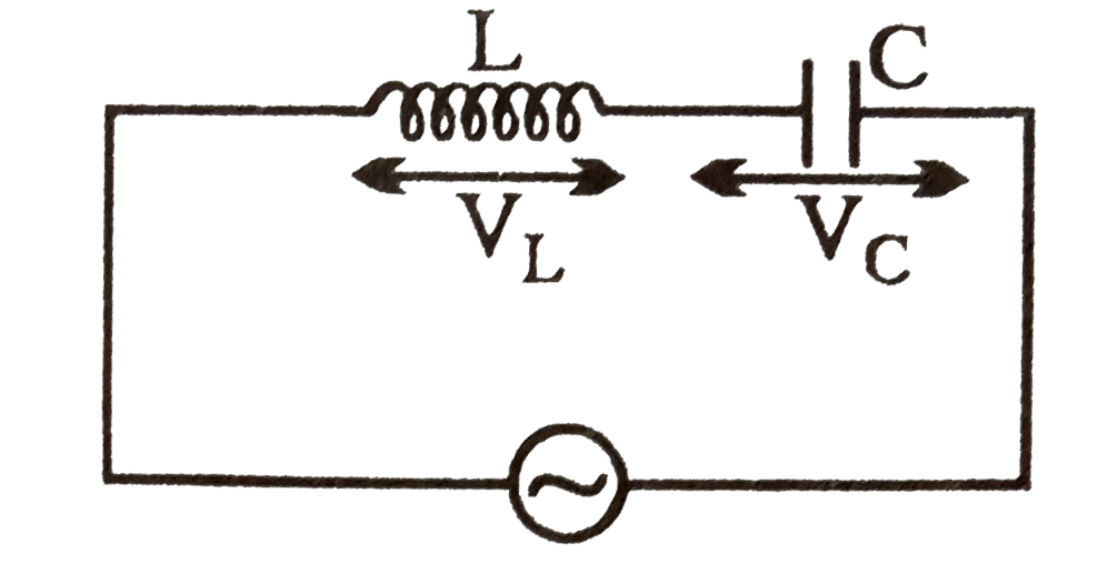
The current I, potential difference VL across the inductor and potential difference VC across the capacitor in circuit as shown in the figure are best represented vectorially as
 A
A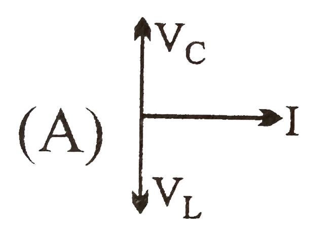 B
B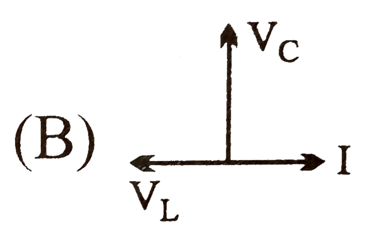 C
C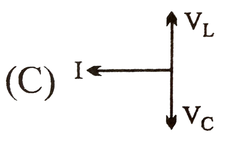 D
D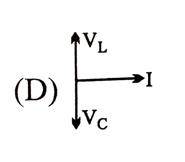
Figure shows the circuit of a flashing lamp, used at construction sites. The fluorescent lamp L, having negligible capacitance, is connected in parallel across the capacitor C of an RC circuit . There is a current through the lamp only when the potential difference across it reaches the breakdown voltage VL). In this event, the capacitor discharges completley through the lamp and lamp flashes momentarily.
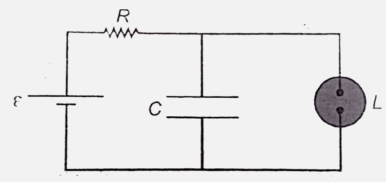
Consider an instant, when the capacitor has just discharged through the flash light. Taking this instant as t=0, the time after which the lamp flashes momentarily is given by
View SolutionAn electric lamp whose resistance is 8 Ω and a conductor of 2 Ω resistance are connected in series to a 5 volt battery . Calculate( a) the total resistance of the circuit (b) the current through the circuit (c) the potential difference across the electric lamp and the conductor?
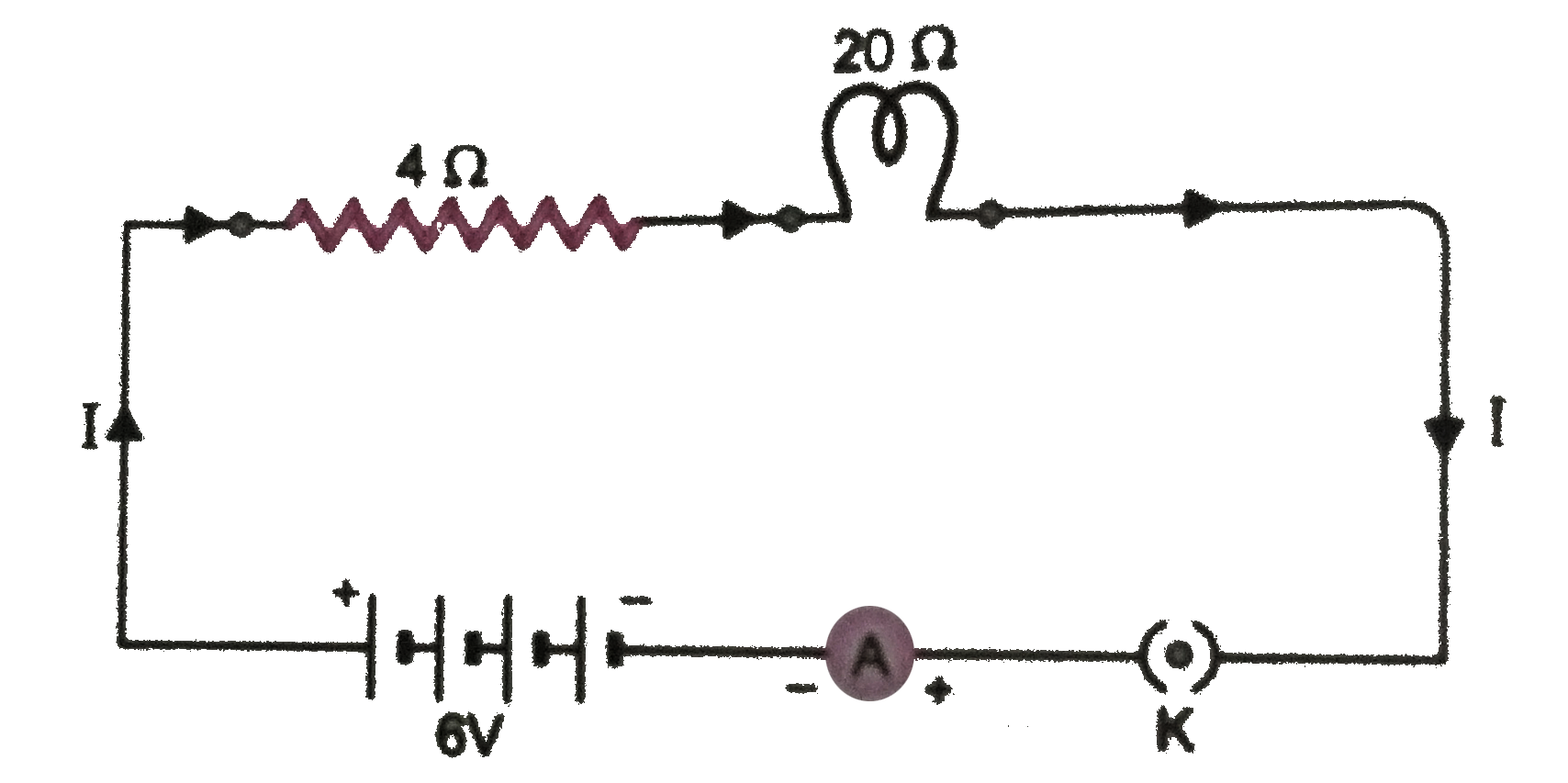
View SolutionAn electric lamp, whose resistance is 20Ω and a conductor of 4Ω resistance are connected to a 6V battery as shown in (Fig. 3.18) Calculate.
(a) the total resistance of the circuit,
(b) the current through the circuit, and
( c) the potential difference across the electric lamp and the conductor.
 .
.
View SolutionAn electric lamp, whose resistance is 20Ω and a conductor of 4Ω resistance are connected to a 6V battery as shown in (Fig. 3.18) Calculate.
(a) the total resistance of the circuit,
(b) the current through the circuit, and
( c) the potential difference across the electric lamp and the conductor.
 .
.
View SolutionA 6 V, 12 W lamp is connected in series with a resistor R and a source of voltage 12 V.
What is the current flowing through the circuit?
View Solution
