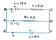
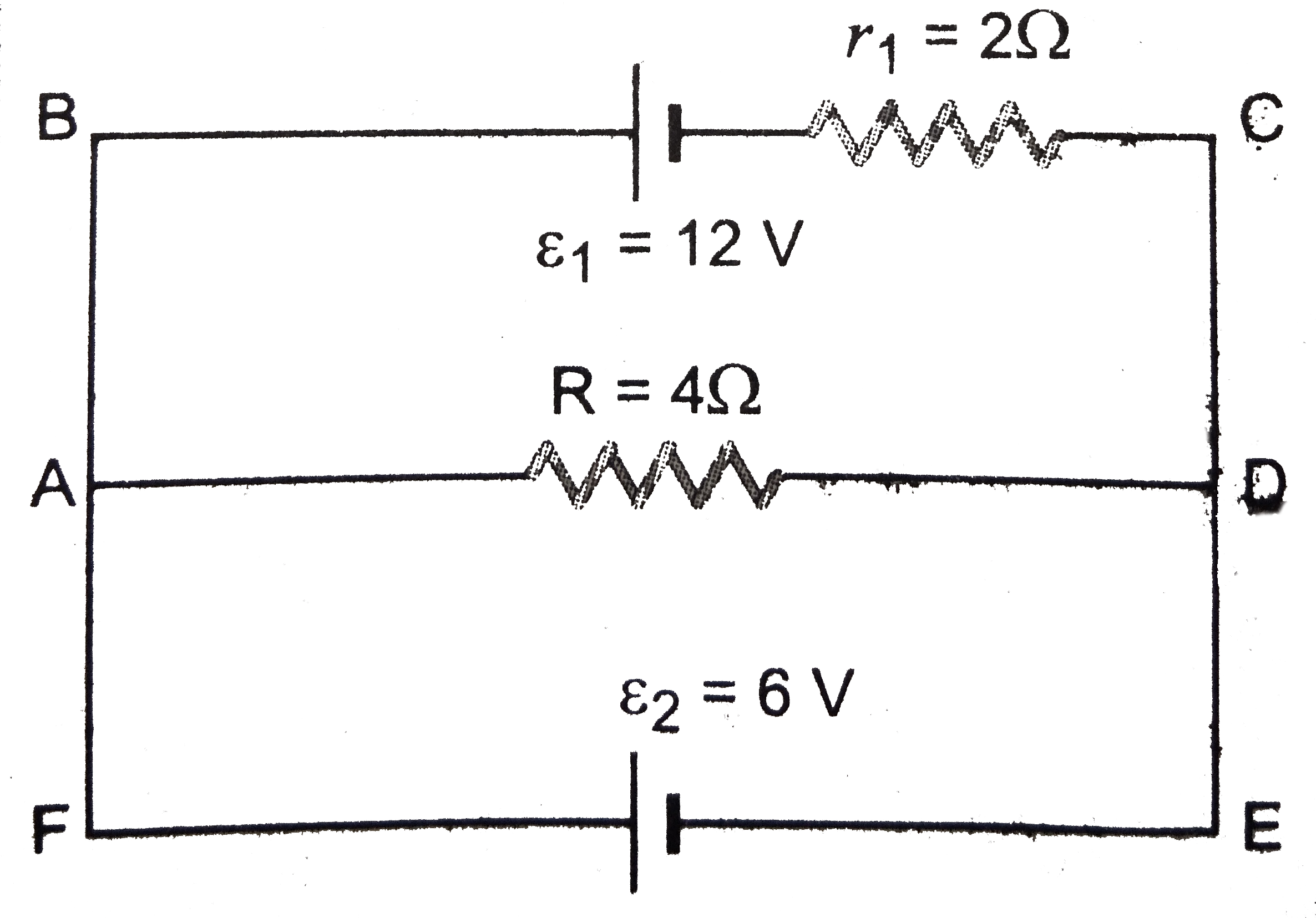
In the electric network shown in the figure use Krichhoff's rules to calculate the power consumed by the resistance R=8Ω

In loop EADFE [Even, data error as per the diagram given] −(I1+I2)8+8=0
I1+I2=1
Power consumerd by the resistance R will be P=(I1+I2)2R=1×8
⇒P=8W
Topper's Solved these Questions
- CURRENT ELECTRICITYBOOK - MODERN PUBLICATIONCHAPTER - CURRENT ELECTRICITYEXERCISE - Objective Type Questions (MULTIPLE CHOICE QUESTIONS) (A. MULTIPLE CHOICE QUESTIONS WITH ONLY ONE CORRECT ANSWER)
36 Videos
- CURRENT ELECTRICITYBOOK - MODERN PUBLICATIONCHAPTER - CURRENT ELECTRICITYEXERCISE - Objective Type Questions (MULTIPLE CHOICE QUESTIONS) (B. MULTIPLE CHOICE QUESTION FOR COMPETITIVE EXAMINATIONS)
20 Videos
- CURRENT ELECTRICITYBOOK - MODERN PUBLICATIONCHAPTER - CURRENT ELECTRICITYEXERCISE - REVISION EXERCISES (LONG ANSWER QUESTIONS)
10 Videos
- ATOMS BOOK - MODERN PUBLICATIONCHAPTER - ATOMS EXERCISE - Chapter Practice Test
16 Videos
- DUAL NATURE OF RADIATION AND MATTER BOOK - MODERN PUBLICATIONCHAPTER - DUAL NATURE OF RADIATION AND MATTER EXERCISE - CHAPTER PRACTICE TEST
15 Videos
Similar Questions
Knowledge Check
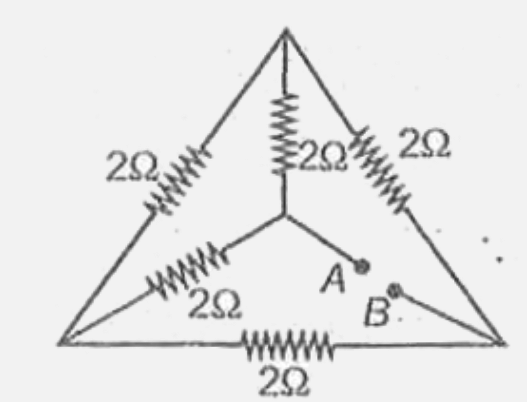
In the network shown in the figure, each of the resistance is equal to 2Ω. The resistance between the points A and B is
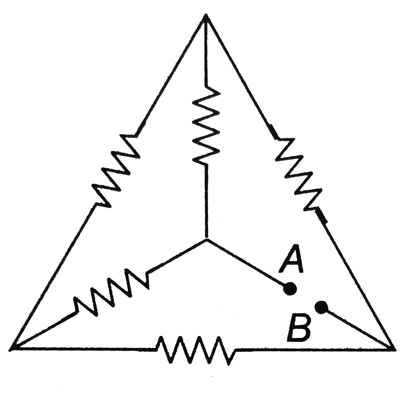 A1ΩB4ΩC3ΩD2Ω
In the electrical network shown in the figure, What will be the potential difference (in volt) across 3Ω resistance ?
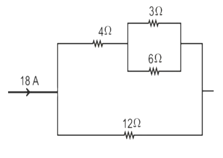
View SolutionIn the electrical network shown in the figure, What will be the potential difference (in volt) across 3Ω resistance ?

View SolutionIf the cell of emf 5 volt shown in the figure gives a power of 10W. Q, find the powers consumed by the resistors 2Ω and 1Ω
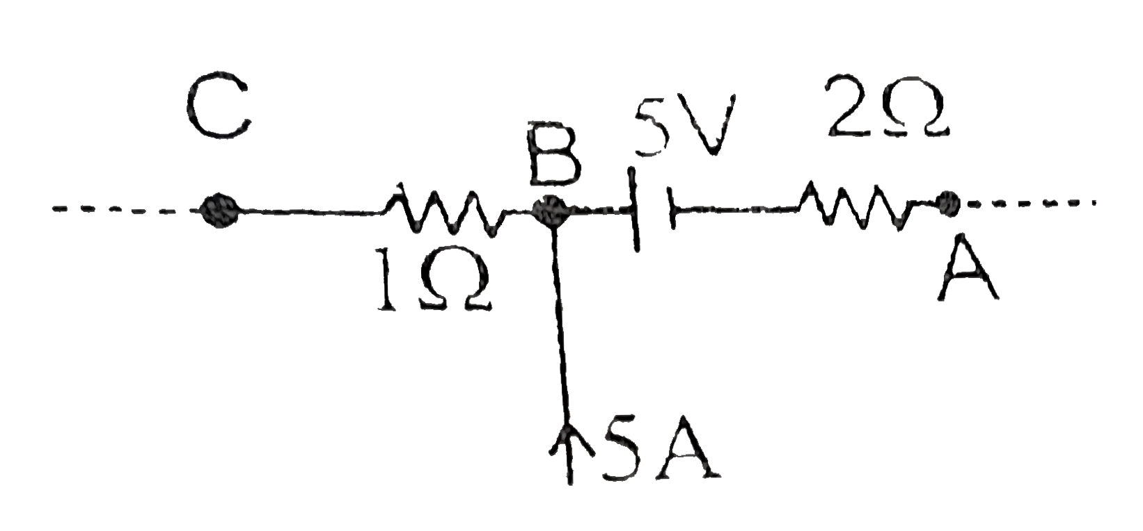
View SolutionIf the cell of emf 5 volt shown in the figure gives a power of 10W. Q, find the powers consumed by the resistors 2Ω and 1Ω

View SolutionTwo resistors R1=60ΩandR2=90Ω are connected in parallel. If electric power consumed by the resistor R1 is 15 W, calculate the power consumed by the resistor R2
View Solution(a) State Kirchhoff's rules for an electric network. Using Krichhoff's rules, obtain the balance condition in terms of the resistances of four arms of Wheatstone bridge,
(b) In the meterbridge experimental set up, shown in the Fig., the null point 'D' is obtained at a distance of 40 cm from end A of the meterbridge wire. If a resistance of 10Ω is connected in series with R1, null point is obtained at AD = 60 cm. Calculate the values of R1 and R2

View SolutionIn the network shown in the figure, each of the resistance is equal to 2Ω . The resistance between the point A and B is
View Solution

