Derive an expression for the impedance of a series LCR circuit connected to an a.c. supplied to the of variable frequency.
Plot a graph showing variation of current with the frequency of the applied voltage. Explain briefly how the phenomenon of resonance in the circuit can be used in the turning mechanism of a radio or TV set.

Let VL,VR,VC and V represent the voltage across the inductor resistor capacitor and the source respectively. VR is parallel to I. VC is π/2 behind I and VL is π/2 ahead of I.
Now
VOR=VOC=i0XC and VOL=I0XL
Clearly V20=V2OR+(VOL−VOC)2
=i20[R2+(XL−XC)2]
Thus i0=V0√R2+(XL−XC)2
Impedance =V0i0=√R2+(XL−XC)2
=√R2+(ωL−1ωC)2

The capacitance of a capacitor in the turning circuit is varied such that the reason and frequency of the circuit becomes nearly equal to the frequency of the radio signal to be received. When this happens the amplitude of the current becomes maximum in the receiving circuit.
Topper's Solved these Questions
- ALTERNATING CURRENTBOOK - OSWAAL PUBLICATIONCHAPTER - ALTERNATING CURRENTEXERCISE - Topic - 2 (Numerical Problem)
11 Videos
- ALTERNATING CURRENTBOOK - OSWAAL PUBLICATIONCHAPTER - ALTERNATING CURRENTEXERCISE - Topic - 3 (Very Short Answer Type Questions)
3 Videos
- ALTERNATING CURRENTBOOK - OSWAAL PUBLICATIONCHAPTER - ALTERNATING CURRENTEXERCISE - Topic - 2 (Short Answer Type Questions -II)
7 Videos
- 2020 Solved Paper I BOOK - OSWAAL PUBLICATIONCHAPTER - 2020 Solved Paper I EXERCISE - Exercise
41 Videos
- ATOMSBOOK - OSWAAL PUBLICATIONCHAPTER - ATOMSEXERCISE - NUMERICAL PROBLEMS
11 Videos
Similar Questions
Derive an expression for the impedance of a series LCR circuit connected to an a.c. supply of variable frequency. Plot a graph showing variation of current with the frequency of the applied voltage. Explain briefly how the phenomenon of resonance in the circuit can be used in the tuning mechanism of a radio or TV set.
View SolutionCalculate the frequency of series resonance circuit. Define Q factor of this circuit. Explain briefly how the phenomenon of resonance in the circuit can be used in the tuning mechanism of a radio or TV set.
View Solution
Knowledge Check
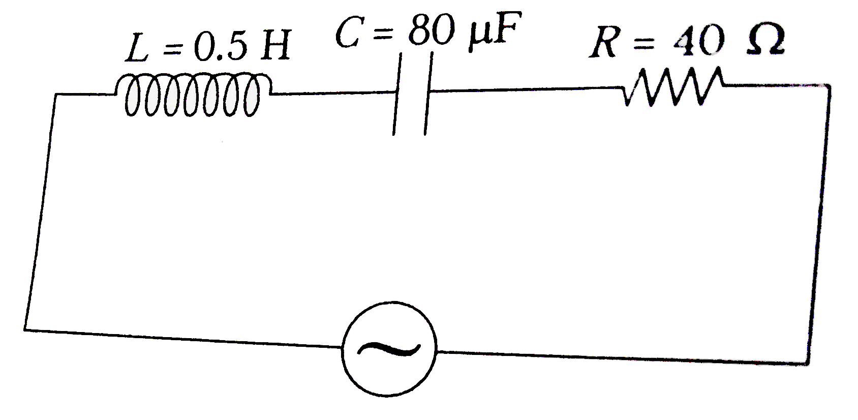
In the given figure , a series L-C-R circuit is connected to a variable frequency source of 230 V . The impedance and amplitude of the current at the resonating frequency will be
 A20Ω and 4.2 AB30Ω and 6.9 AC25Ω and 5.8 AD40Ω and 5.75 A
Figure shows a series LCR circuit connected to a variable frequency 230 V source.

The source frequency which drives the circuit the circuit in resonance isA4 HzB5 HzC6 HzD8 HzFigure shows a series LCR circuit connected to a variable frequency 230 V source.

The source frequency which drives the circuit the circuit in resonance isA4 HzB5 HzC6 HzD8 Hz
Sketch a graph showing the variation of impedance of LCR circuit the frequency of applied voltage.
View SolutionMention the factors on which the resonant frequency of a series LCR circuit depends. Plot a graph showing variation of impedance of a series LCR circuit with the frequency of the applied a.c. source.
View SolutionIn the given figure , a series L-C-R circuit is connected to a variable frequency source of 230 V . The impedance and amplitude of the current at the resonating frequency will be

View SolutionDraw a labelled graph showing variation of impedance of a series LCR circuit with frequency of the a.c. supply.
View SolutionSeries LCR circuit is connected to an AC source of angular frequency ω. Current flowing in the circuit is found to lead the voltage by π/4. Magnitude of capacitance is
View Solution
