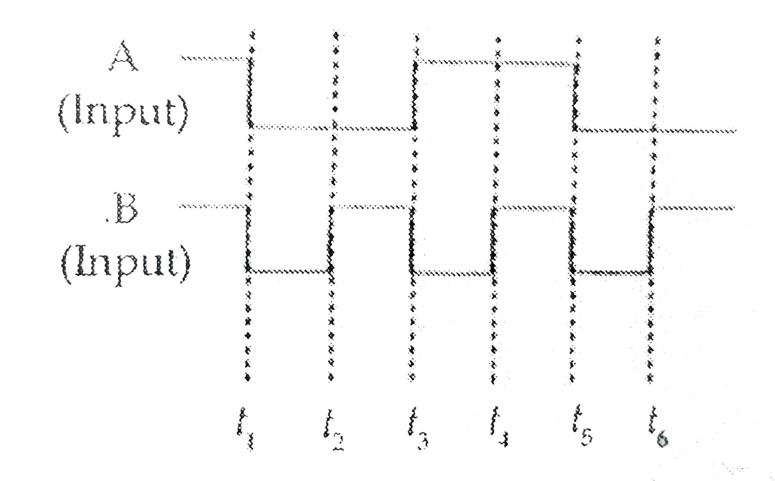
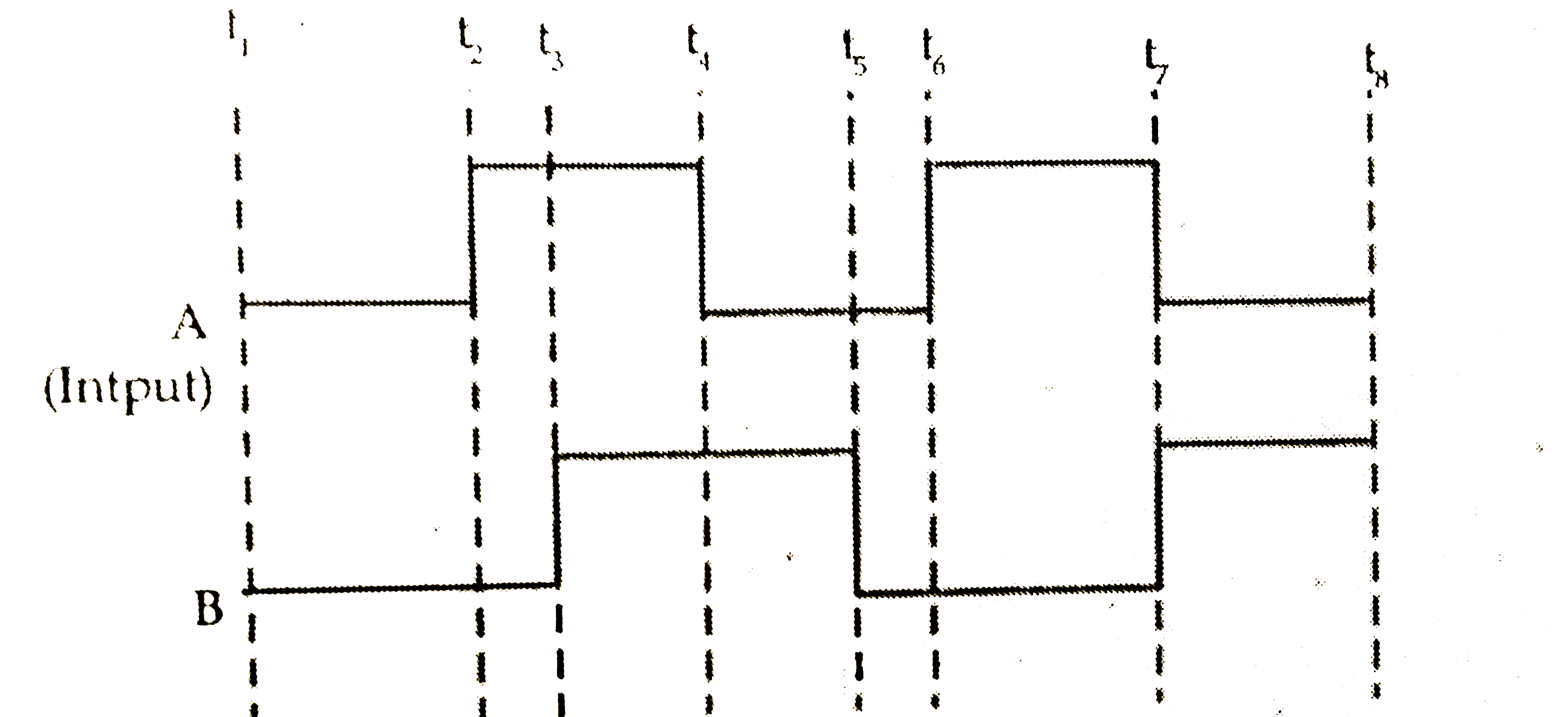
The given input A, B are fed to a 2-input NAND gate. Draw the output wave form of the gate
For the NAND gate, the Boolean expression is,
Y=¯A.B=¯A+¯B
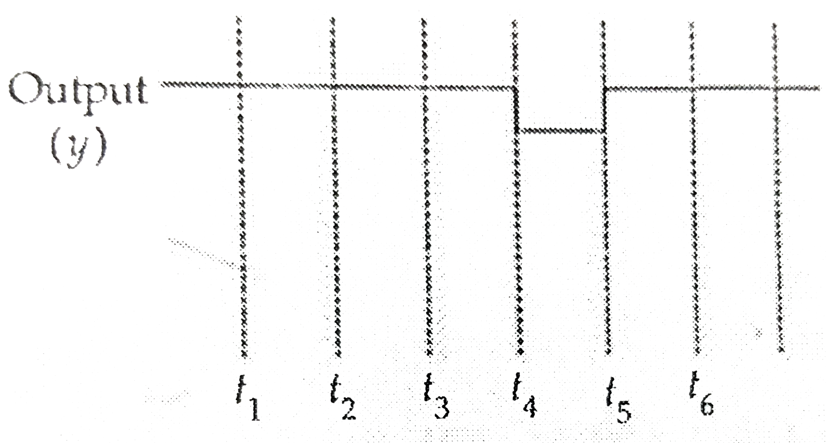
For the given wave form, we have the following values for A, B and Y:
For time ttot1,A=1,B=1∴Y=0+0=0
t2 to t2,A=0,B=1∴Y=1+0=1
t3 to t4,A=1,B=0∴Y=0+1=1
t4 to t5,A=1,B=1∴Y=0+0=0
t5 to t6,A=0,B=0∴Y=1+1=1
t6 to t7,A=0,B=1∴Y=1+0=1
Thus, the wave form for output y is given in the figure.
Topper's Solved these Questions
- XII BOARDSBOOK - XII BOARDS PREVIOUS YEARCHAPTER - XII BOARDSEXERCISE - SET II
9 Videos
- XII BOARDSBOOK - XII BOARDS PREVIOUS YEARCHAPTER - XII BOARDSEXERCISE - SET III
9 Videos
- XII BOARDSBOOK - XII BOARDS PREVIOUS YEARCHAPTER - XII BOARDSEXERCISE - SECTION - B
9 Videos
- SAMPLE PAPER 2019BOOK - XII BOARDS PREVIOUS YEARCHAPTER - SAMPLE PAPER 2019EXERCISE - SECTION D
6 Videos
Similar Questions
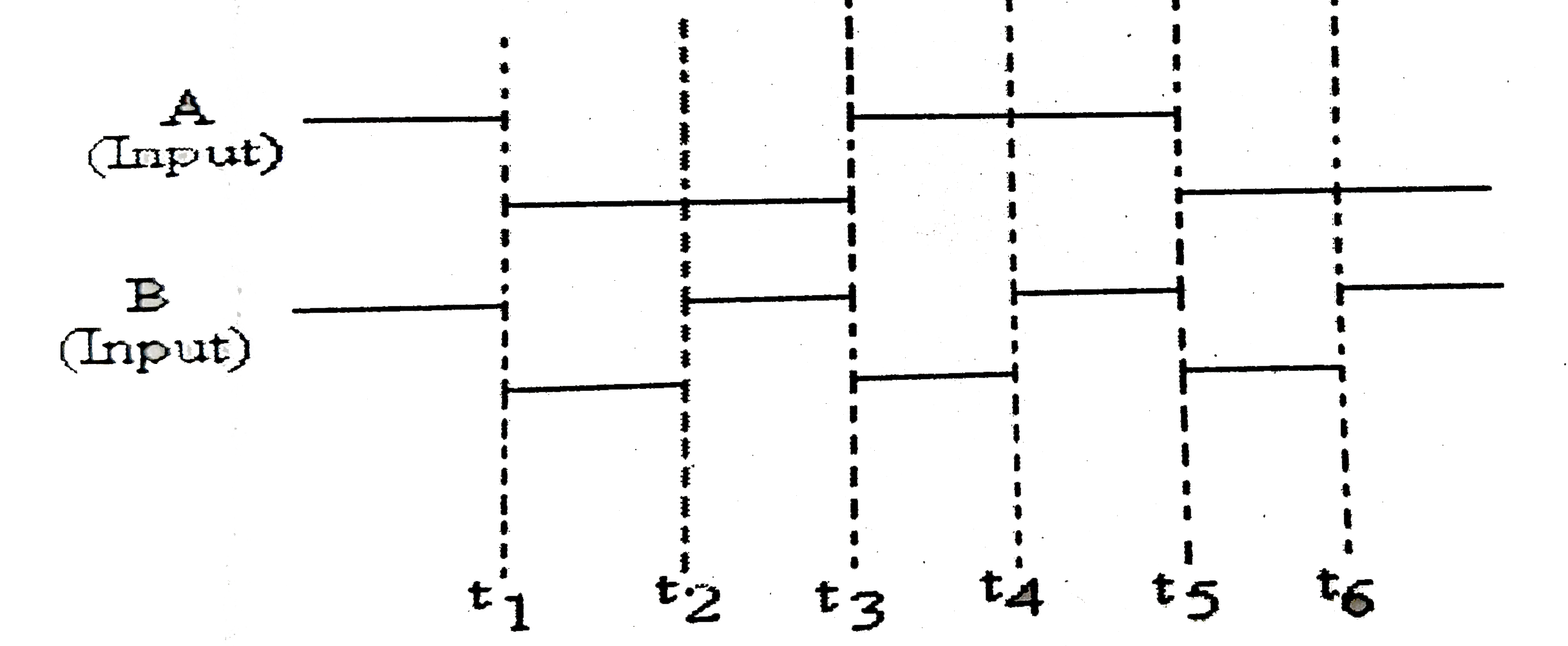
The give inputs A, B are fed to a 2-input NAND gate. Draw the output wave form of the gate.
View Solution
The give inputs A, B are fed to a 2-input NAND gate. Draw the output wave form of the gate.
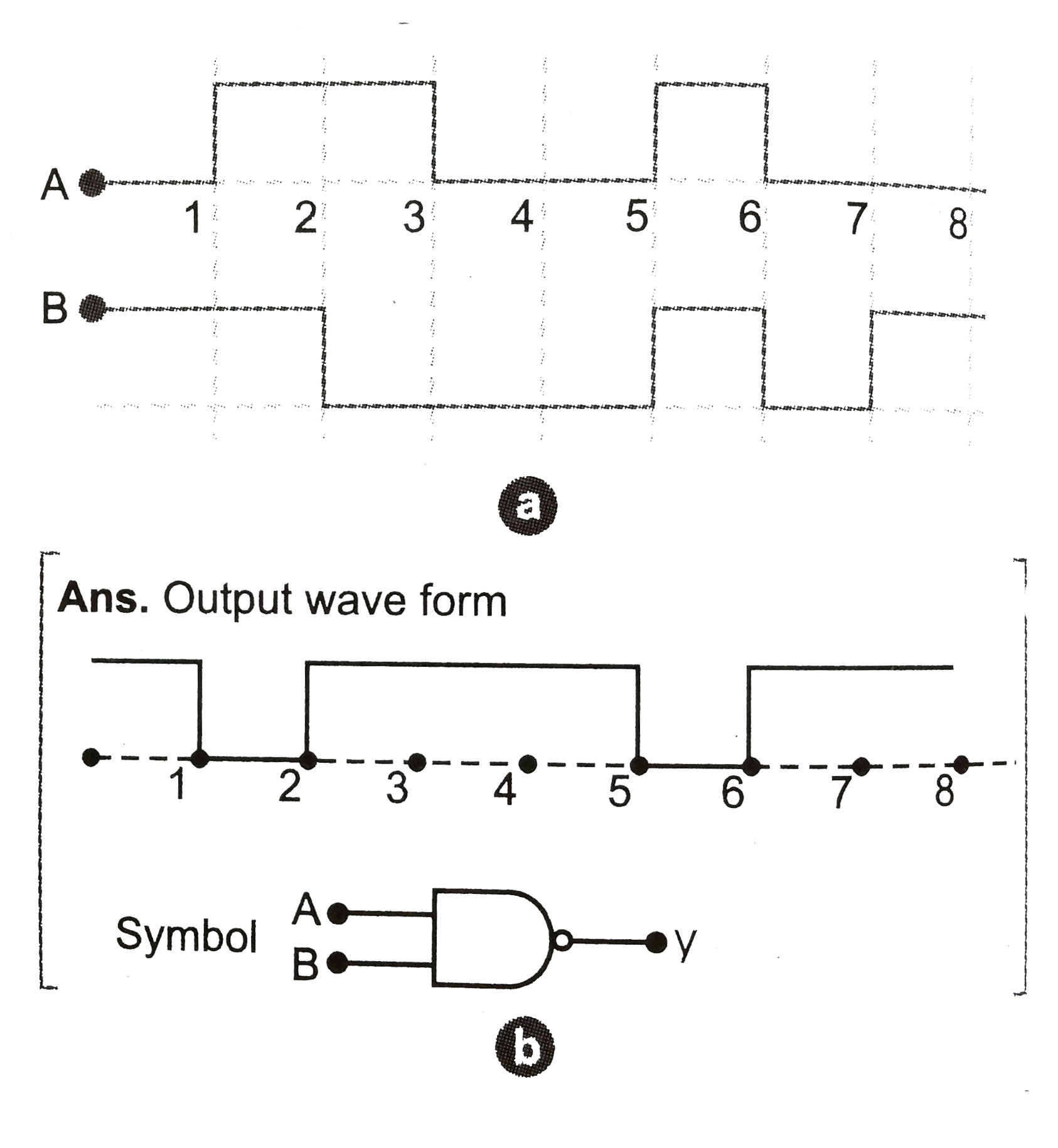
View SolutionTwo signal A and B shown in the Fig. are used as two inputs of a NAND gate. Draw its output wave form. Give the logic symbol of NAND gate.
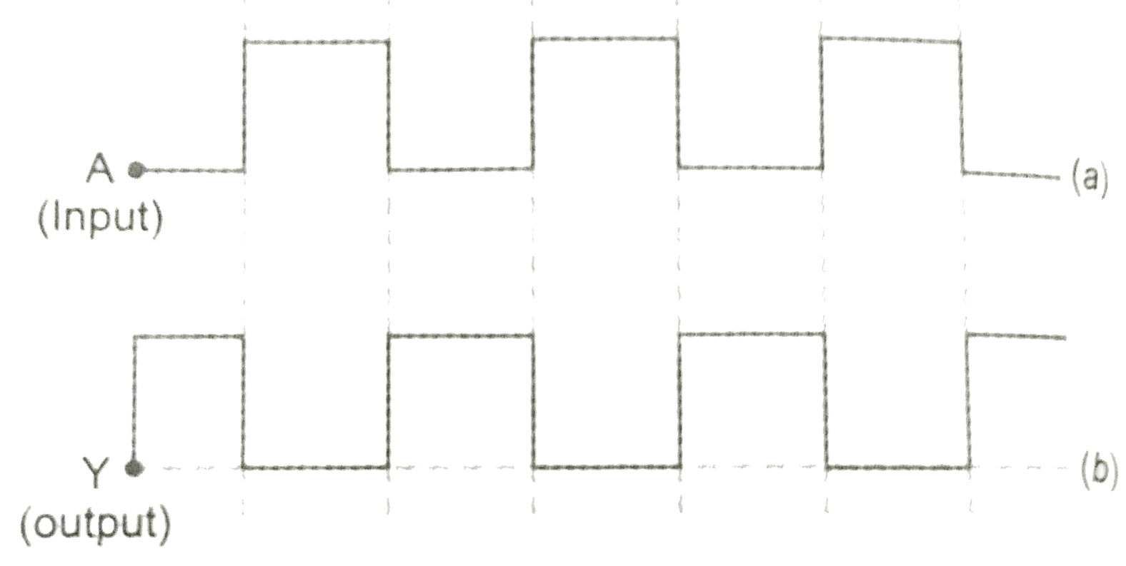
View SolutionThe input wave form for NOT gate is shown in Fig.Draw the output wave form of this gate.
View SolutionThe Fig shown input waveforms A and B to a logic gate. Draw the output waveform for an OR gate. Write the truth table for this logic gate and draw its logic symbol.
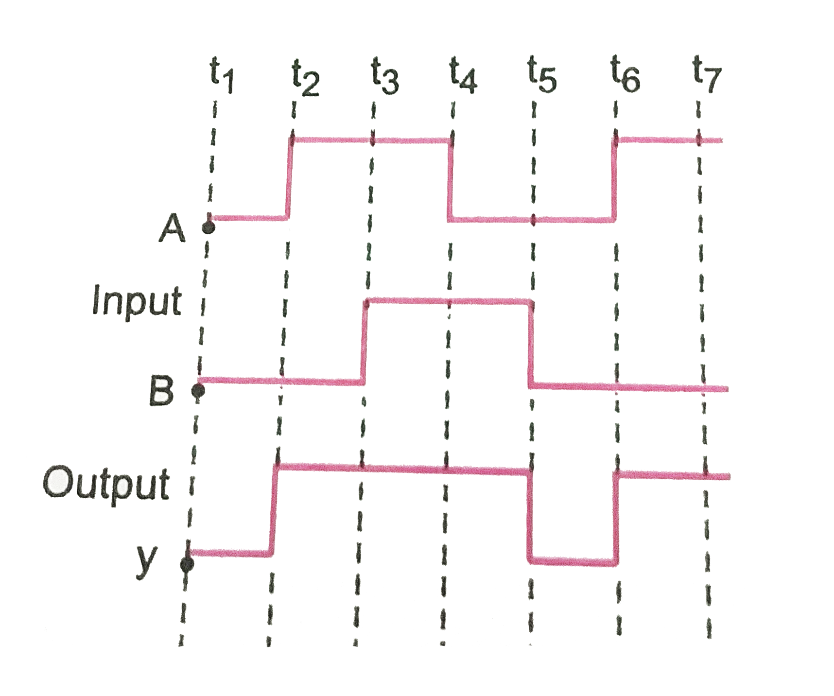
View SolutionThe Fig shown input waveforms A and B to a logic gate. Draw the output waveform for an OR gate. Write the truth table for this logic gate and draw its logic symbol.

View SolutionTwo signals A, and B shown in Fig. are used as two inputs of an AND gate obtain its output wave form. Draw the logic symblo of AND gate.
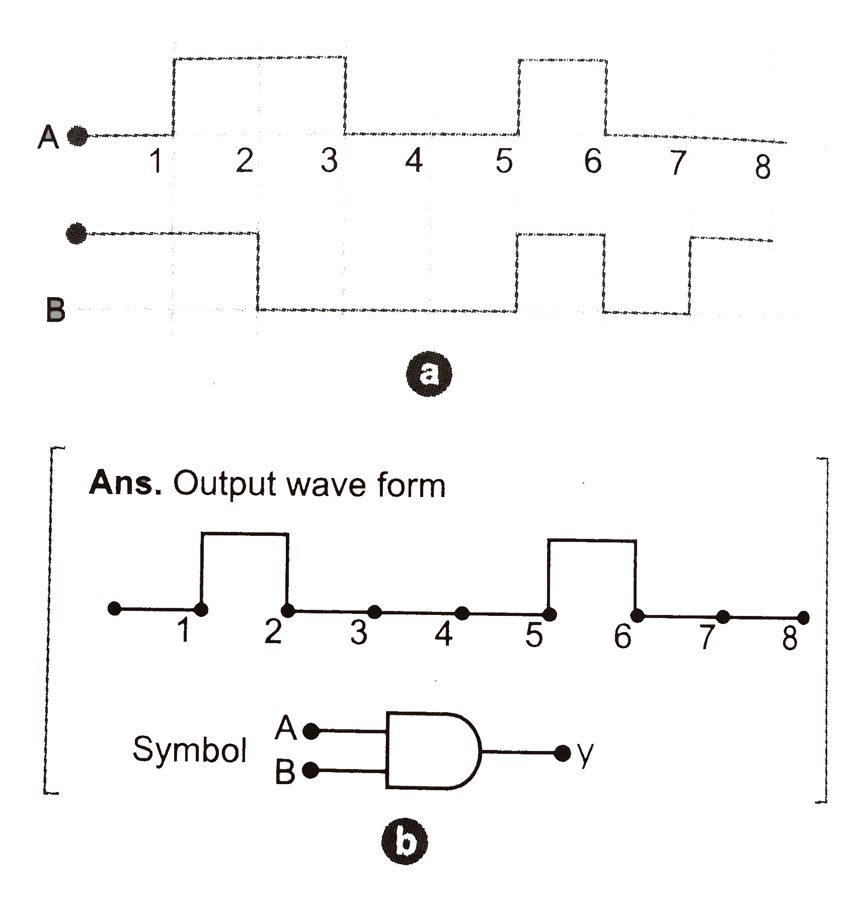
View SolutionThe Fig.shows the input wavwforms A and B for 'AND' gate. Draw the output waveform and write the truth table for this logic gate.
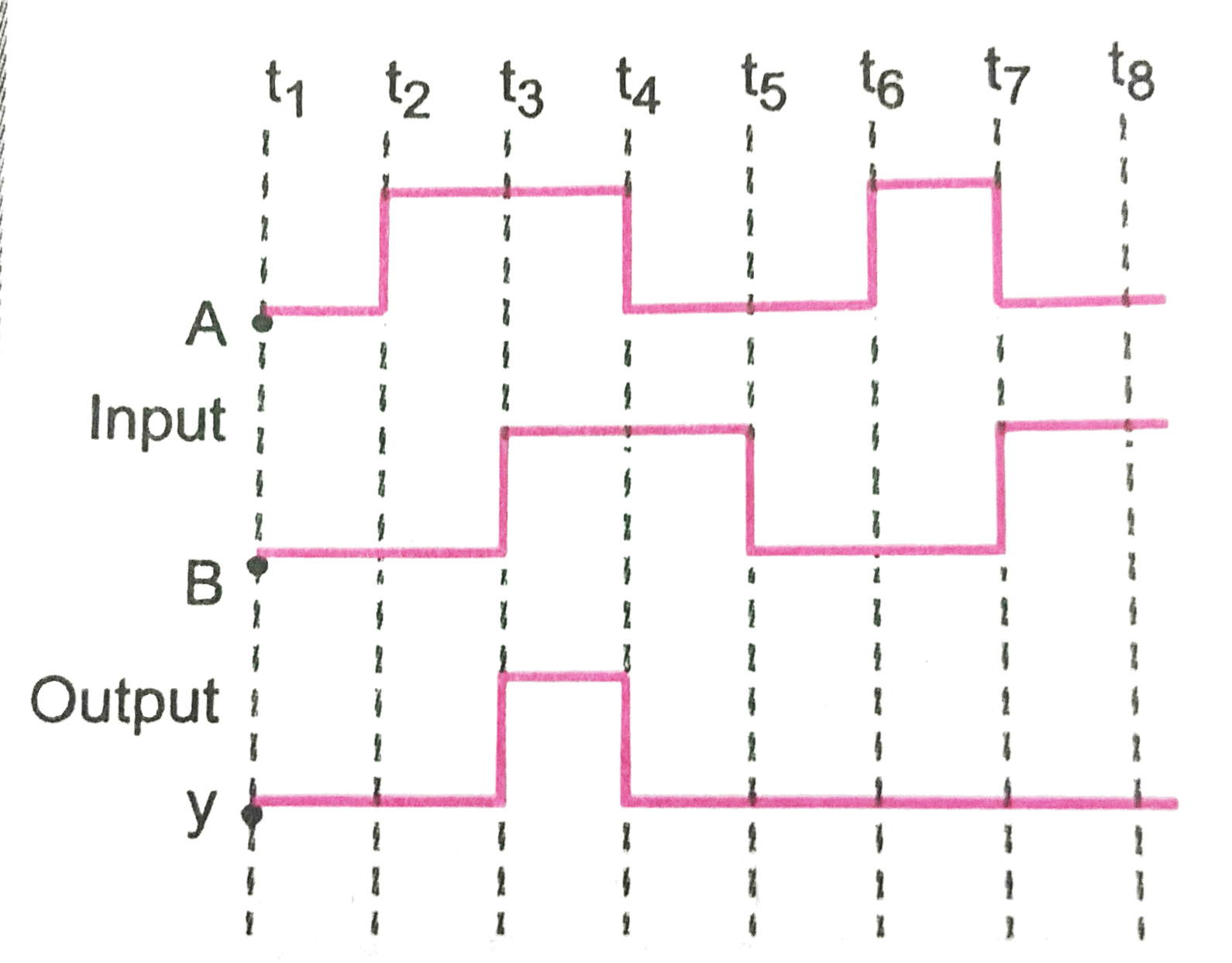
View SolutionThe figure shows the input weveforms A and B for 'AND' gate Draw the output waveform and write the truth table for this logic gate
 .
.
View SolutionUsing the wave forms of the input A and B, draw the output waveform of the given logic circuit . Identify the logic gate obtained . Write also the truth table.

View Solution
