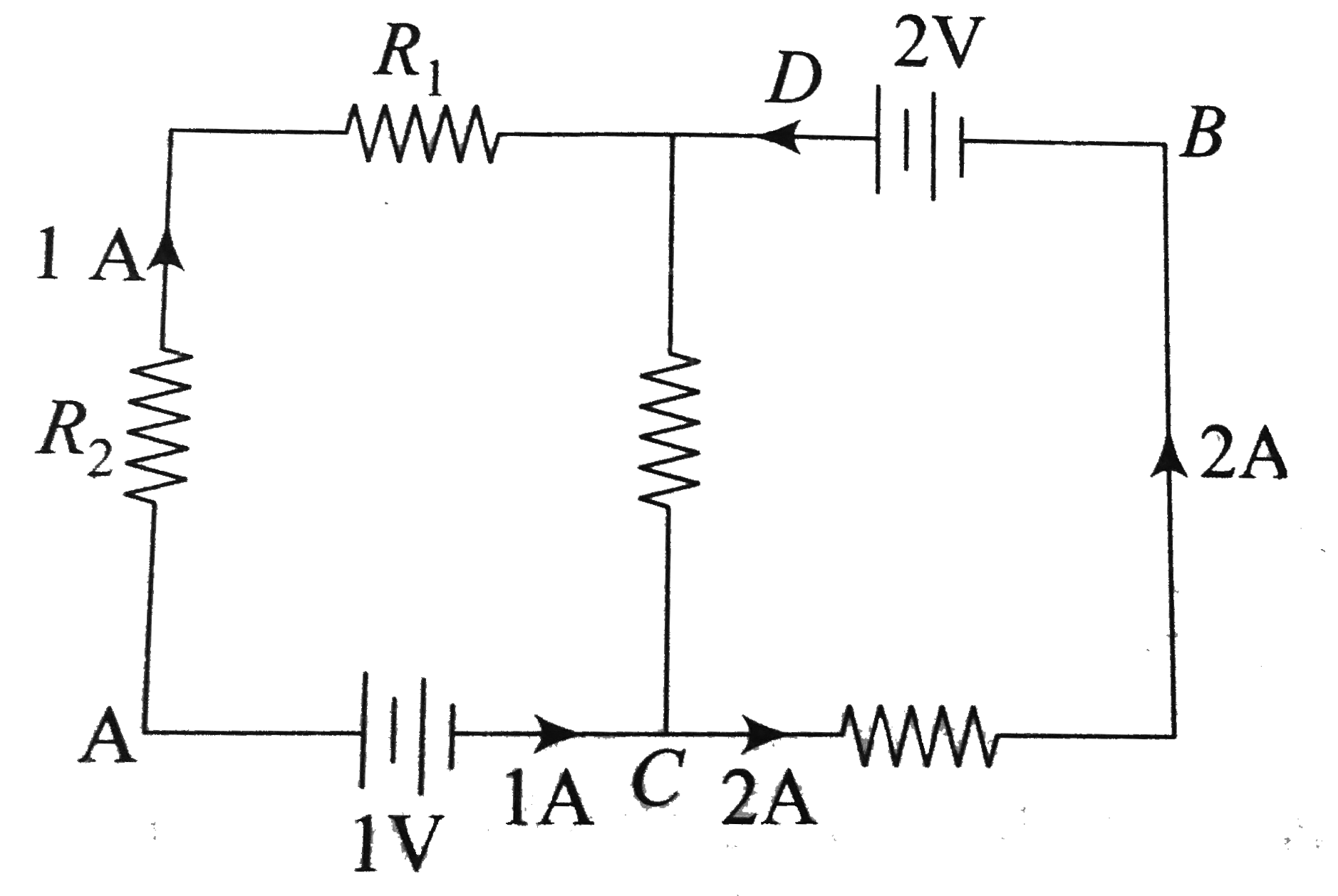
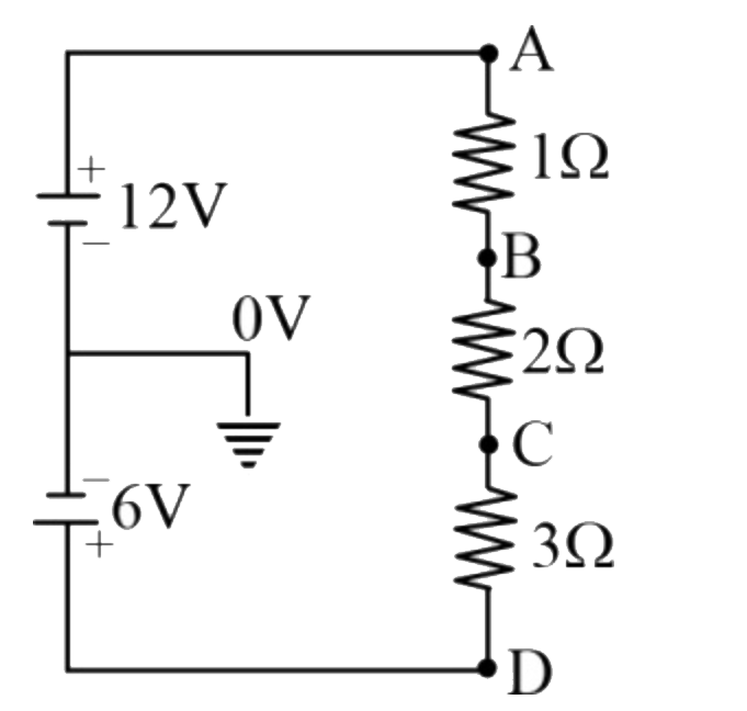
In the circuit shown in the figure, if the potential at point A is taken to be zero, the potential at point B is

A
+1V
B
−1V
C
+2V
D
−2V
Text Solution
The correct Answer is:A

Applying Kirchhoff voltage law in the circuit as shown in the figure.
∴VA+1+2(1)−2=VB
0+1=VB(∵VA=0V (Given))
VB=+1V

|
Topper's Solved these Questions
- CURRENT ELECTRICITY BOOK - MTG GUIDECHAPTER - CURRENT ELECTRICITY EXERCISE - CHECK YOUR NEET VITALS
16 Videos
- ATOMS AND NUCLEIBOOK - MTG GUIDECHAPTER - ATOMS AND NUCLEIEXERCISE - AIPMT/NEET(MCQs)
40 Videos
- DUAL NATURE OF MATTER AND RADIATION BOOK - MTG GUIDECHAPTER - DUAL NATURE OF MATTER AND RADIATION EXERCISE - AIPMT/ NEET MCQs
30 Videos
Similar Questions
Knowledge Check
In the circuit shown in the figure, if potentail at point A is taken to be zero, the potential at point B is
 A−1VB+2VC−2VD+1V
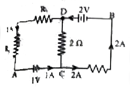
In the circuit shown in the figure, if the potential at point A behind to be zero, the potential at point B is :
 A−1VB+2VC−2VD+1V
In a circuit shown in the figure, what is potential of point A?
 A2VB5VC8VD4V
In the given circuit the potential at point B is zero, the potential at points A and D will be

View SolutionIn the given circuit the potential at point B is zero, the potential at points A and D will be

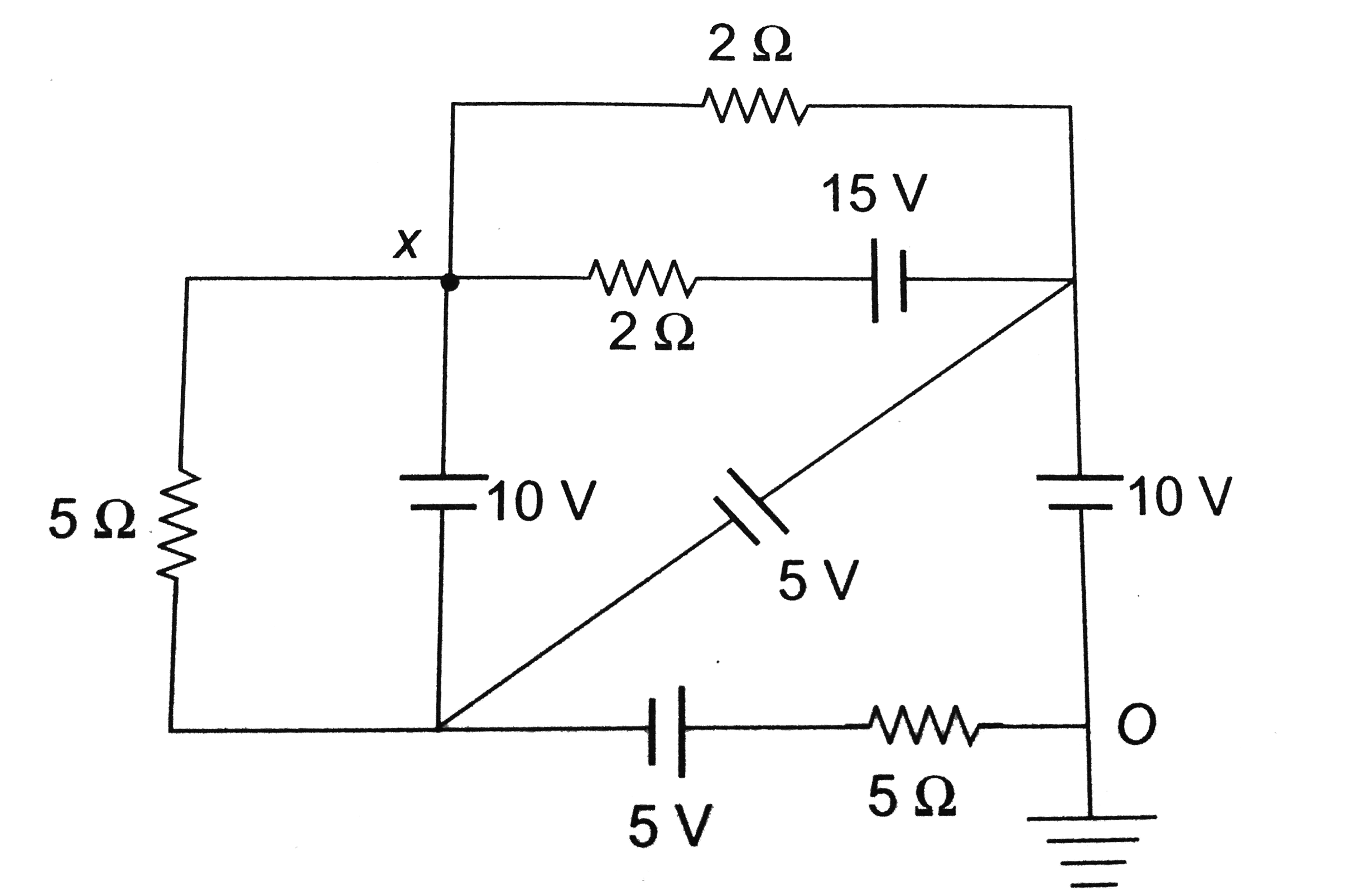
View SolutionIn the circuit shown if point O is earthed, the potential of point X is equal to
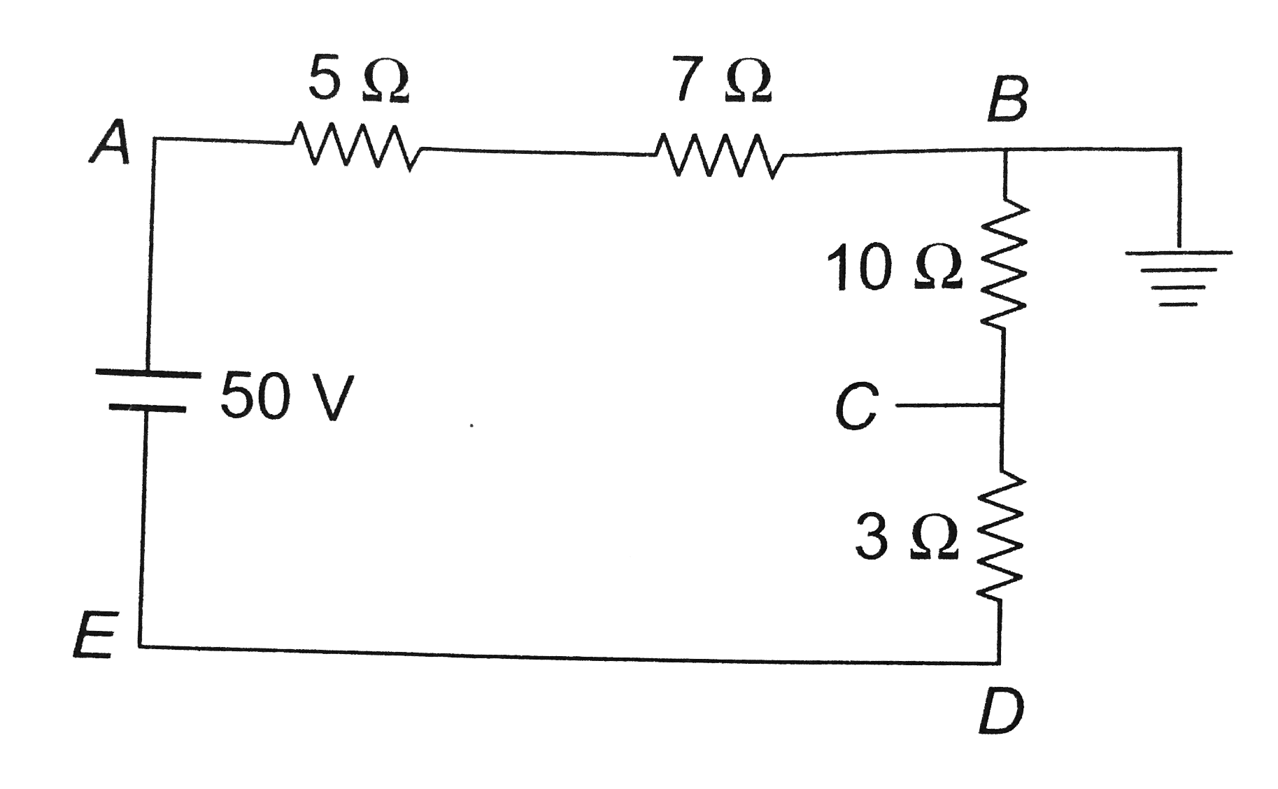
View SolutionIn the circuit shown, the point B is earthed. The potential at the point 'A' is
View SolutionIn the circuit diagram shown in figure, the potentials of the points B, C and D are respectively.
View Solution
