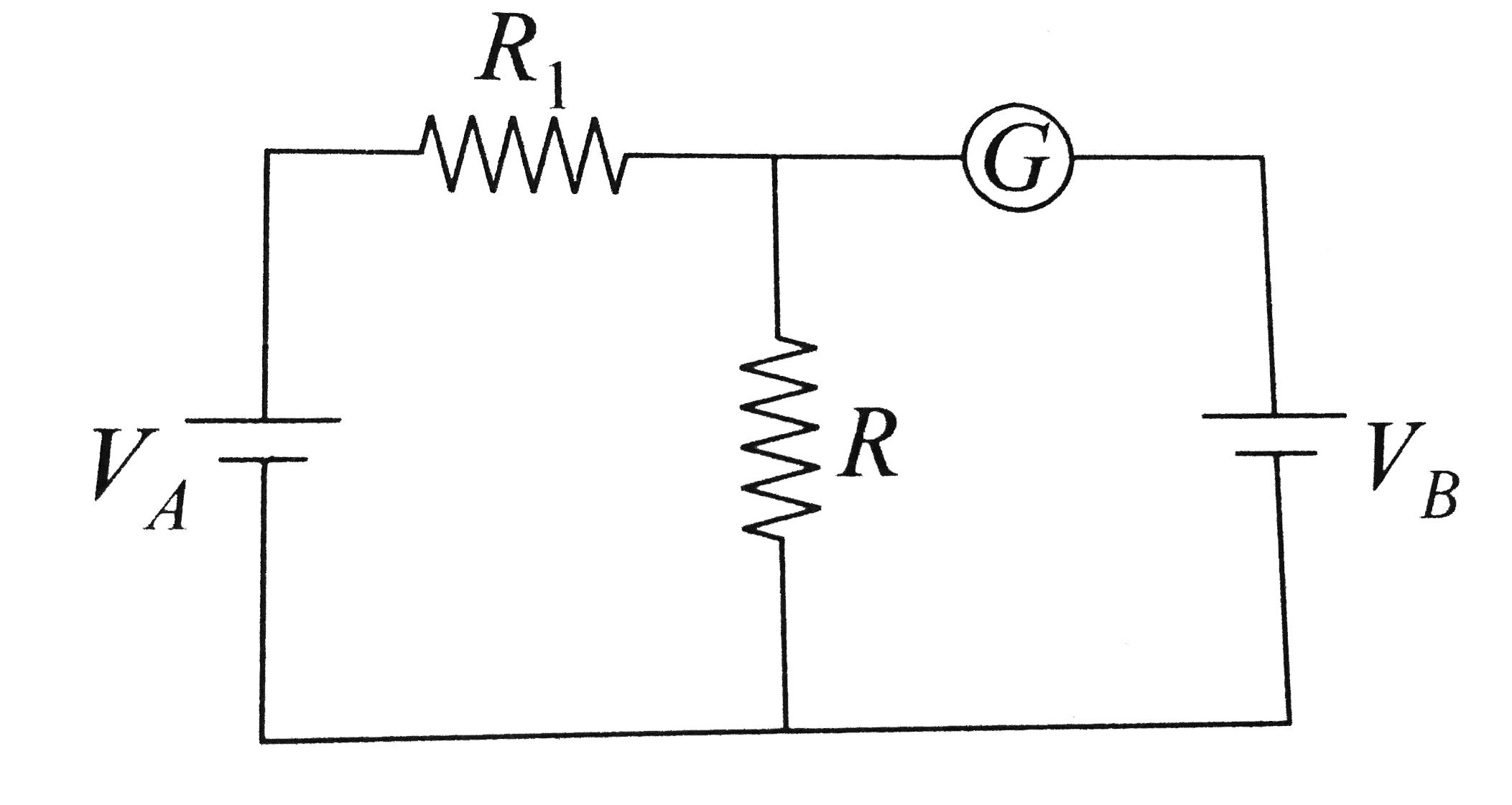
In the circuit shown, the cells A and B have negligible resistance. For VA=12V,R1=500ΩandR=100Ω, the galvanometer (G) shows no deflection. The value of VB is

4V
2V
12V
6V
The correct Answer is:B
Since the galvanometer shows no deflection so current will flow as shown in the figure.
Current, I=VAR1+R=12V(500+100)Ω=12600A
VB=IR=(12600A)(100Ω)=2V

Topper's Solved these Questions
- CURRENT ELECTRICITY BOOK - MTG GUIDECHAPTER - CURRENT ELECTRICITY EXERCISE - CHECK YOUR NEET VITALS
16 Videos
- ATOMS AND NUCLEIBOOK - MTG GUIDECHAPTER - ATOMS AND NUCLEIEXERCISE - AIPMT/NEET(MCQs)
40 Videos
- DUAL NATURE OF MATTER AND RADIATION BOOK - MTG GUIDECHAPTER - DUAL NATURE OF MATTER AND RADIATION EXERCISE - AIPMT/ NEET MCQs
30 Videos
Similar Questions
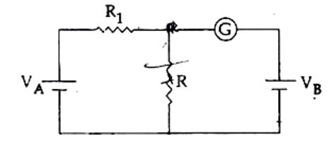
In the circuit shown the cells A and B have negligible resistance. For VA=12V,R1=500Ω and R=100Ω, the galvanometer (G) shows no deflection. The value of VB is
View SolutionIn the circuit shown the cells A and B have negligible resistance. For VA=12V,R1=500Ω and R=100Ω, the galvanometer (G) shows no deflection. The value of VB is

View Solution
Knowledge Check
In the circuit shown the cells A and B have negligible resistance. For VA=12V,R1=500Ω and R=100Ω, the galvanometer (G) shows no deflection. The value of VB is
 A6VB4VC2VD12V
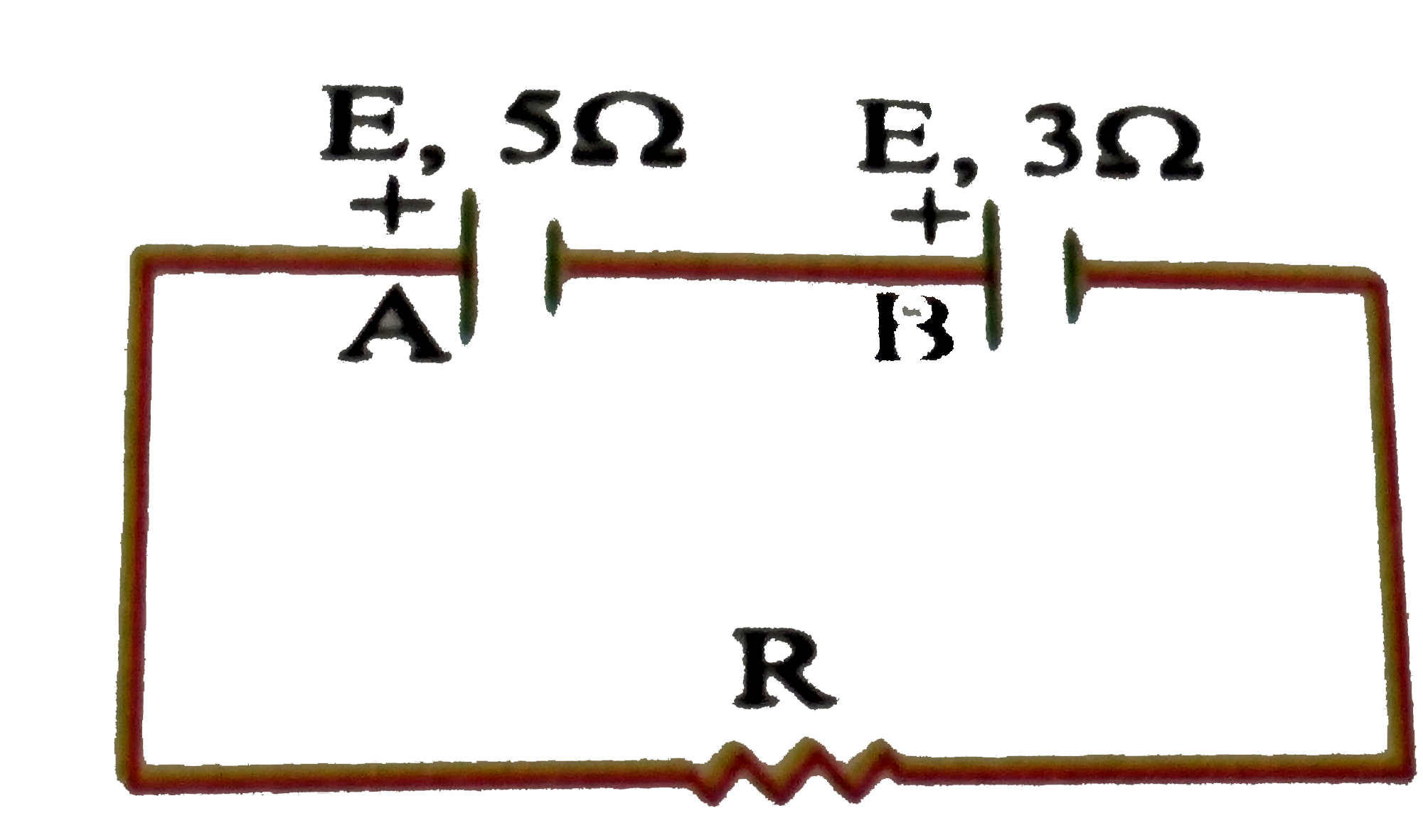
In the circuit shown here, cells A and B have emf 10 V each and the internal resistance is 5Ω for A and 3Ω for B. For what value of R will the potential difference across thhe cell A will be zero?AzeroB1ohmC2ohmD3ohm
In the circuit shown the cells A and B have negligible resistance. For VA=12V,R1=500Ω and R=100Ω the galvanometer (G) shows no deflection. The value of VB is
View SolutionIn the given circuit the internal resistance of the 18 V cell is negligible. If R1=400Ω and the reading of an ideal voltmeter across R4 is 5V, then the value of R2 will be :
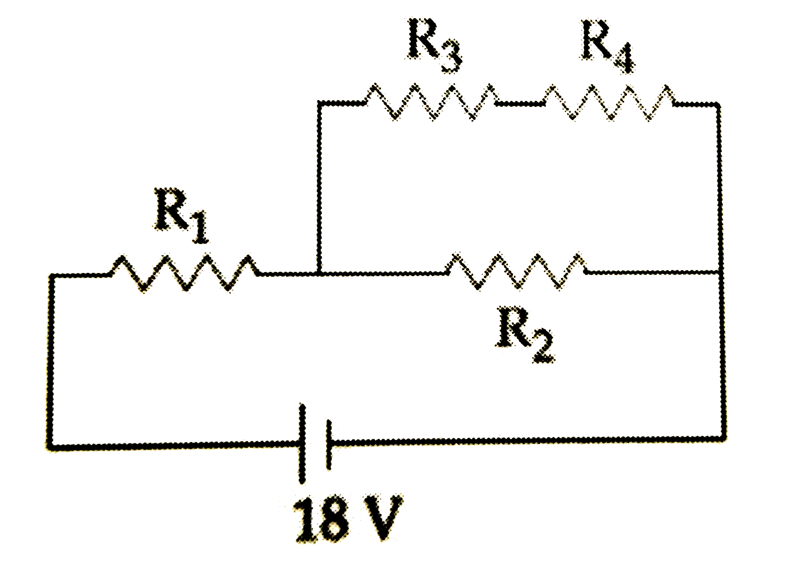
View SolutionIn the given circuit the internal resistance of the 18 V cell is negligible. If R1=400Ω and the reading of an ideal voltmeter across R4 is 5V, then the value of R2 will be :

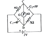
View SolutionIn the circuit shown in Fig., the cell is ideal with e.m.f = 2V. The resistance of the coil of the galvanometer G is 1Ω. Then
View SolutionIn the circuit shown E,F,G and H are cells of emf 2V,1V,3V and 1V respectively and their internal resistance are 2Ω,1Ω,3Ω and 1Ω respectively.
View SolutionIn the circuit shown E,F,G and H are cells of emf 2V,1V,3V and 1V respectively and their internal resistance are 2Ω,1Ω,3Ω and 1Ω respectively.

View Solution
