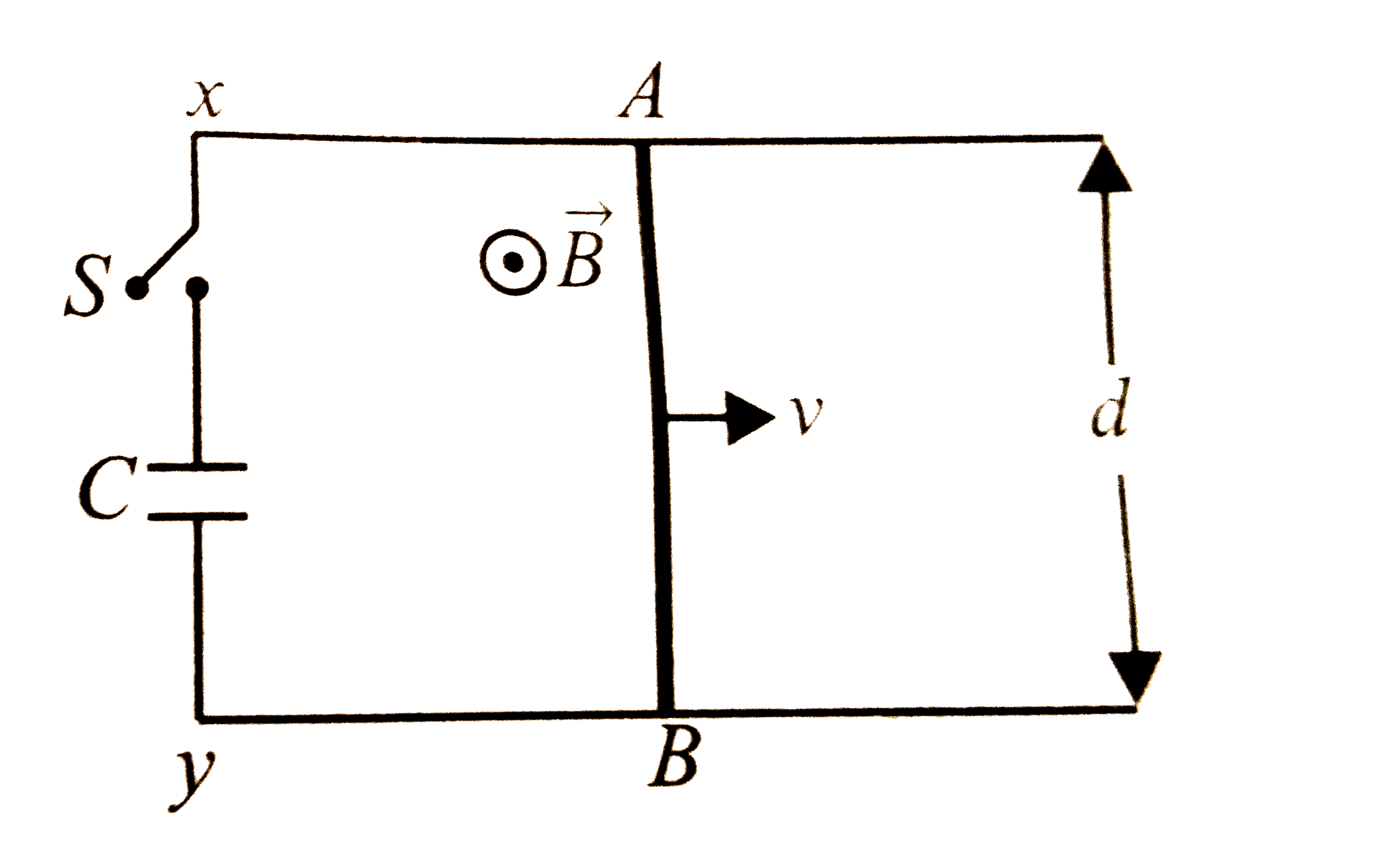
Find the current in the sliding rod AB (resistance = R) for the arranged shown in Fig. B is constant and is out of the paper. Paralllel wires have no resistance. υ is constant. Switch is closed at time t = 0.
To find the current in the sliding rod AB, we will follow a step-by-step approach based on the principles of electromagnetic induction.
Step 1: Understand the Setup
We have a sliding rod AB with resistance R, moving with a constant velocity V in a magnetic field B that is perpendicular to the plane of motion. The distance between the two parallel wires is d.
Hint: Identify the direction of motion and the magnetic field to determine the induced EMF.
Step 2: Calculate the Induced EMF
The induced electromotive force (EMF) in the rod due to its motion in the magnetic field is given by the formula:
E=B⋅V⋅d
Since the angle between the velocity V and the magnetic field B is 90∘, we can simplify this to:
E=B⋅V⋅d
Hint: Remember that the induced EMF is proportional to the product of the magnetic field strength, the velocity of the rod, and the length of the rod.
Step 3: Apply Ohm's Law
The current I flowing through the rod can be calculated using Ohm's Law:
I=ER
Substituting the expression for E from the previous step:
I=B⋅V⋅dR
Hint: Ohm's Law relates voltage (or EMF) to current and resistance.
Step 4: Consider the Capacitor Effect
When the switch is closed at t=0, the capacitor will start charging. The current in the circuit will not only depend on the induced EMF but also on the charge Q on the capacitor and its capacitance C. The relationship can be expressed as:
dQdt=I−QRC
Where I is the current due to the induced EMF.
Hint: The capacitor will affect the current as it charges, leading to a differential equation involving the charge Q.
Step 5: Solve the Differential Equation
Rearranging the equation gives:
RCdQdt+Q=I
This is a first-order linear differential equation. We can solve it using integrating factors or separation of variables.
Hint: Look for integrating factors or consider the standard form of a first-order linear differential equation.
Step 6: Integrate and Find the Charge Q
After integrating, we find:
Q(t)=A(1−e−t/RC)
Where A is a constant related to the induced EMF.
Hint: The solution will involve an exponential decay function, characteristic of charging capacitors.
Step 7: Find the Current I(t)
The current in the rod can be found by differentiating Q(t):
I(t)=dQdt=ARCe−t/RC
Substituting A=B⋅V⋅dR:
I(t)=B⋅V⋅dR2Ce−t/RC
Hint: Differentiating the charge function gives the current, and the exponential term reflects the charging behavior of the capacitor.
Final Result
The current in the sliding rod AB at time t is given by:
I(t)=B⋅V⋅dR2Ce−t/RC
This expression shows how the current evolves over time as the capacitor charges.
We have a sliding rod AB with resistance R, moving with a constant velocity V in a magnetic field B that is perpendicular to the plane of motion. The distance between the two parallel wires is d.
The induced electromotive force (EMF) in the rod due to its motion in the magnetic field is given by the formula:
E=B⋅V⋅d
Since the angle between the velocity V and the magnetic field B is 90∘, we can simplify this to:
E=B⋅V⋅d
The current I flowing through the rod can be calculated using Ohm's Law:
I=ER
Substituting the expression for E from the previous step:
I=B⋅V⋅dR
When the switch is closed at t=0, the capacitor will start charging. The current in the circuit will not only depend on the induced EMF but also on the charge Q on the capacitor and its capacitance C. The relationship can be expressed as:
dQdt=I−QRC
Where I is the current due to the induced EMF.
Rearranging the equation gives:
RCdQdt+Q=I
This is a first-order linear differential equation. We can solve it using integrating factors or separation of variables.
After integrating, we find:
Q(t)=A(1−e−t/RC)
Where A is a constant related to the induced EMF.
The current in the rod can be found by differentiating Q(t):
I(t)=dQdt=ARCe−t/RC
Substituting A=B⋅V⋅dR:
I(t)=B⋅V⋅dR2Ce−t/RC
The current in the sliding rod AB at time t is given by:
I(t)=B⋅V⋅dR2Ce−t/RC
Topper's Solved these Questions
- ELECTROMAGNETIC INDUCTION BOOK - NCERT EXEMPLAR ENGLISHCHAPTER - ELECTROMAGNETIC INDUCTION EXERCISE - Short answer type questions
5 Videos
- ELECTRIC CHARGES AND FIELDBOOK - NCERT EXEMPLAR ENGLISHCHAPTER - ELECTRIC CHARGES AND FIELDEXERCISE - Long Answer Type Question
6 Videos
- ELECTROMAGNETIC WAVESBOOK - NCERT EXEMPLAR ENGLISHCHAPTER - ELECTROMAGNETIC WAVESEXERCISE - LONG ANSWER
5 Videos
Similar Questions
A sliding rod AB of resistance R is shown in the figure. Here magnetic field B is constant and is out of the paper. Parallel wires have no resistance and the rod is moving with constant velocity v. The current in the sliding rod AB when switch S is closed at time t=0 is
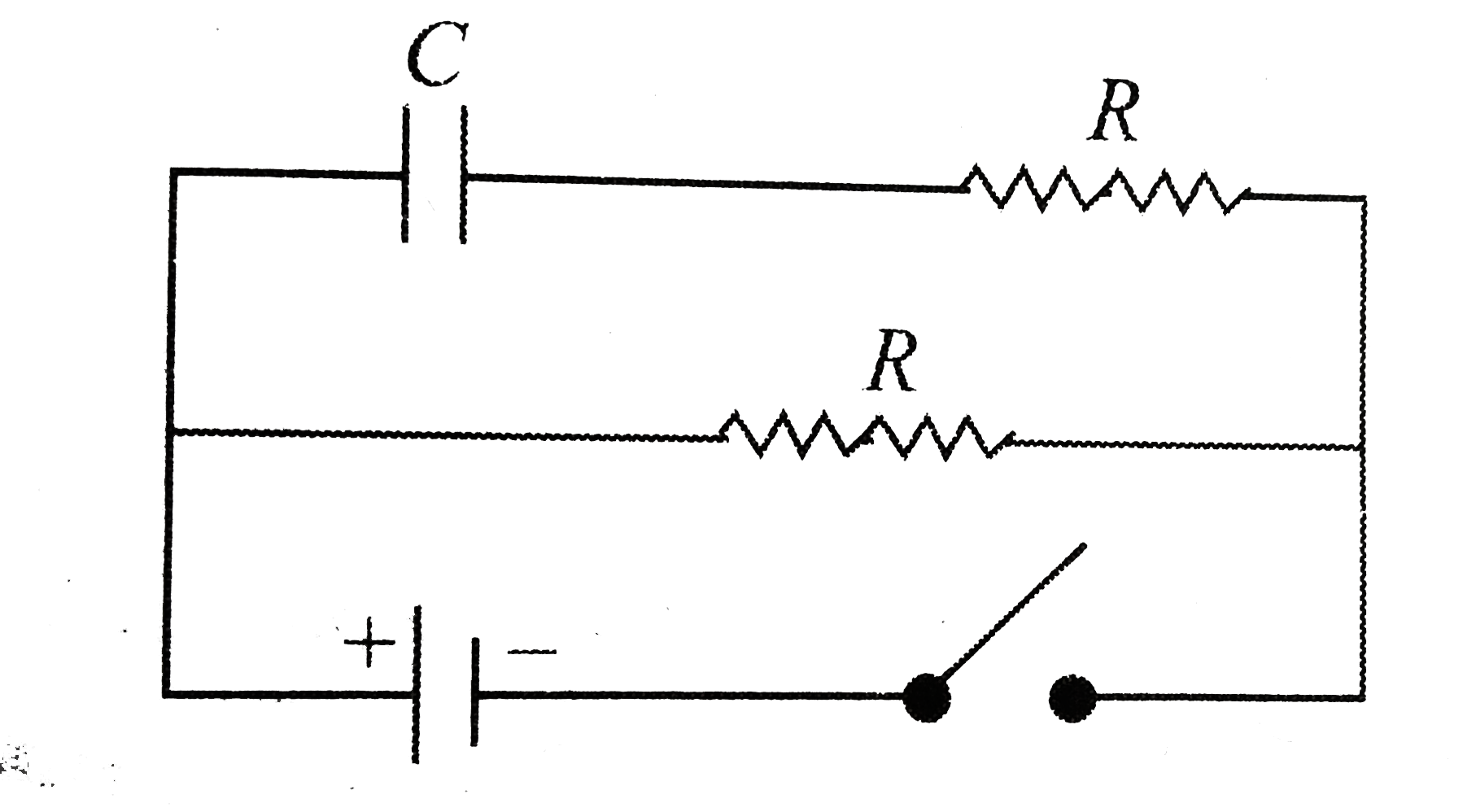
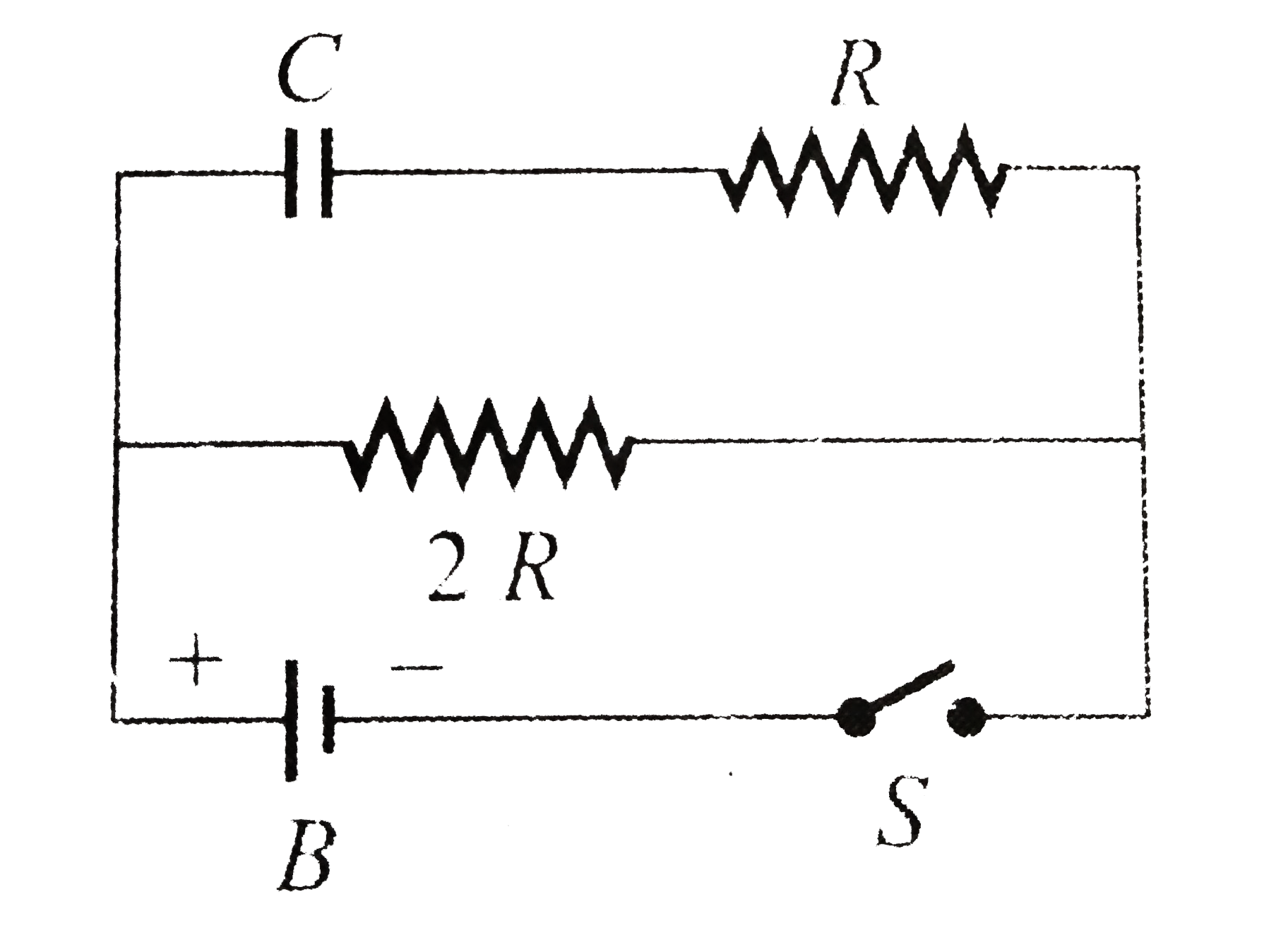
View SolutionIn the circuit shown in fig. when the switch is closed, the capacitor charges with a time constant
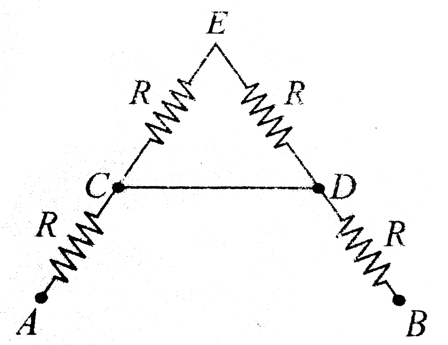
View SolutionFour identical resistances each having value R are arranged as shown in Figure. Find the equivalent resistance between A and B.
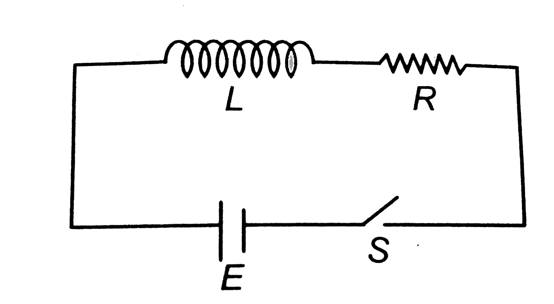
View SolutionIn the circuit shown in figure switch S is closed at time t=0. The charge which passes through the battery in one time constant is
View SolutionIn the circuit shown in fig, if the switch S is closed at t=0 , the capacitor charges with a time constant
View SolutionRelation between current in a conductor and time is shown in fig.
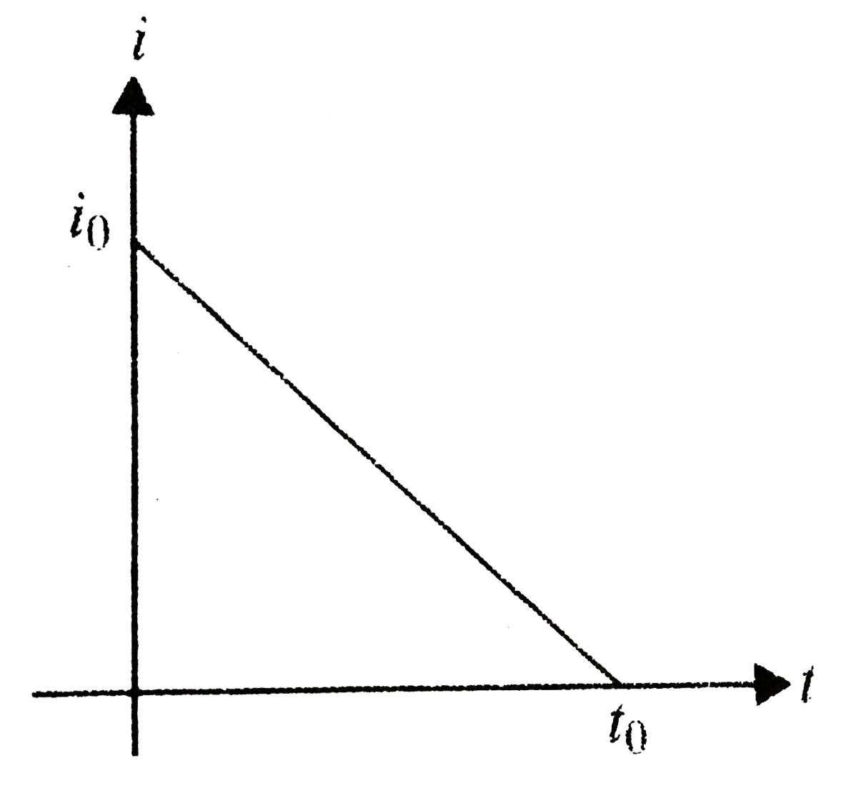
If the resistance of the conductor is R, then the total heat disspipated across resistance R is
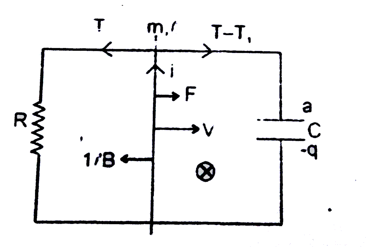
View SolutionFind the velocity of the moving rod at time t if the initial velocity of the rod is zero and a constant force F is applied on the rod.Neglect the resistance of the rod.
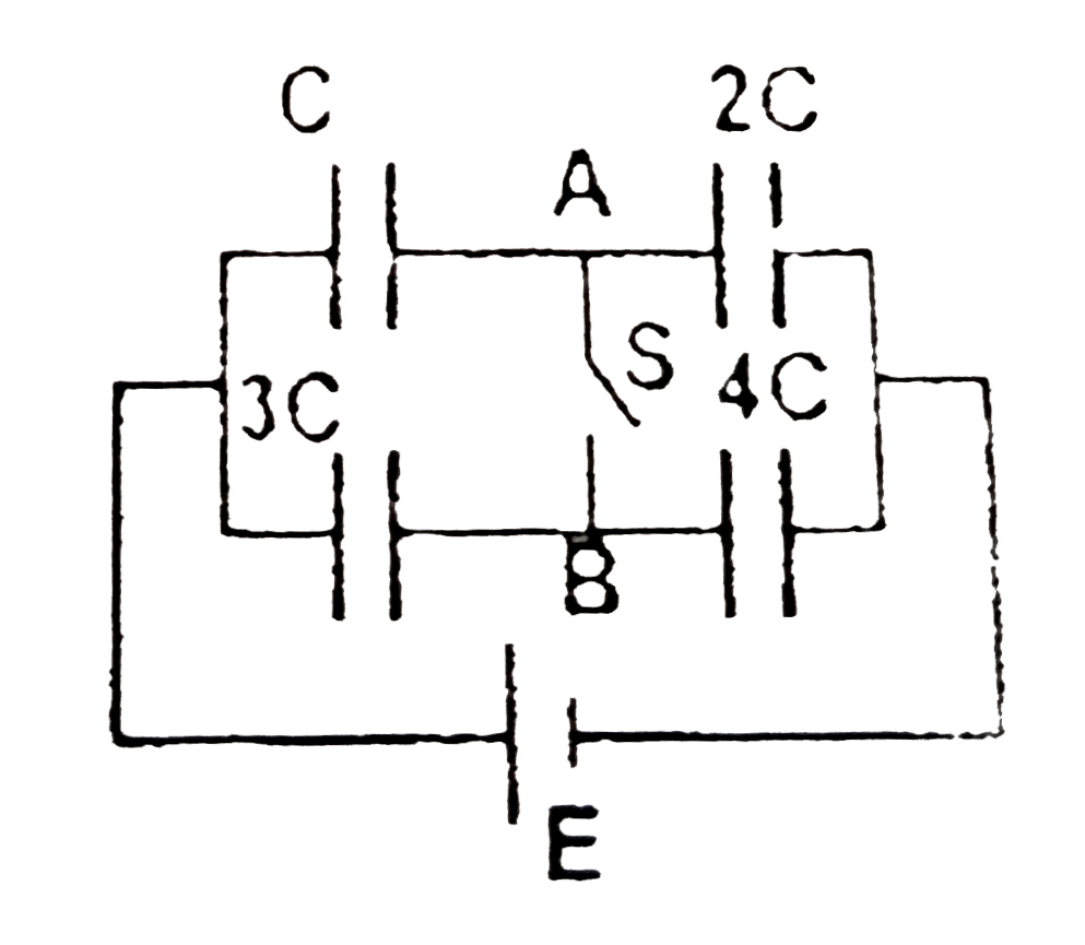
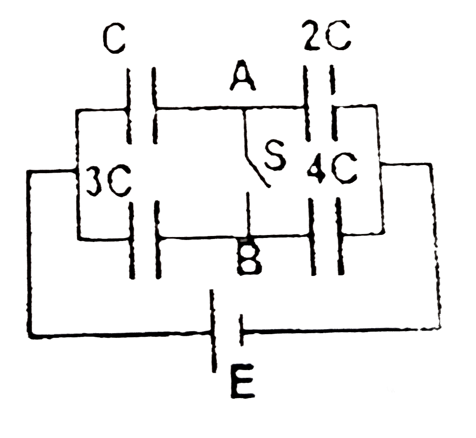
View SolutionFour capacitors of capacitance C, 2C, 3C & 4C respectively are connected as shown in figure. Battery is deal and all the connected wires have no resistance capcitance or inductance. Initially the switch S is open. If at t=0 switch S is closed
Heat generated is the switch after closing switch is
View Solution
Three blocks of masses 6 kg, 4 kg and 2 kg are pulled on a rough surface by applying a constant force 20 N. The values of coefficient of friction between blocks and suface are shown in figure.
Q. Friction force on 6 kg block is
View SolutionFour capacitors of capacitance C, 2C, 3C & 4C respectively are connected as shown in figure. Battery is ideal and all the connected wires have no resistance capcitance or inductance. Initially the switch S is open. If at t=0 switch S is closed
The charge flown through connector AB after switch is closed is
View Solution
