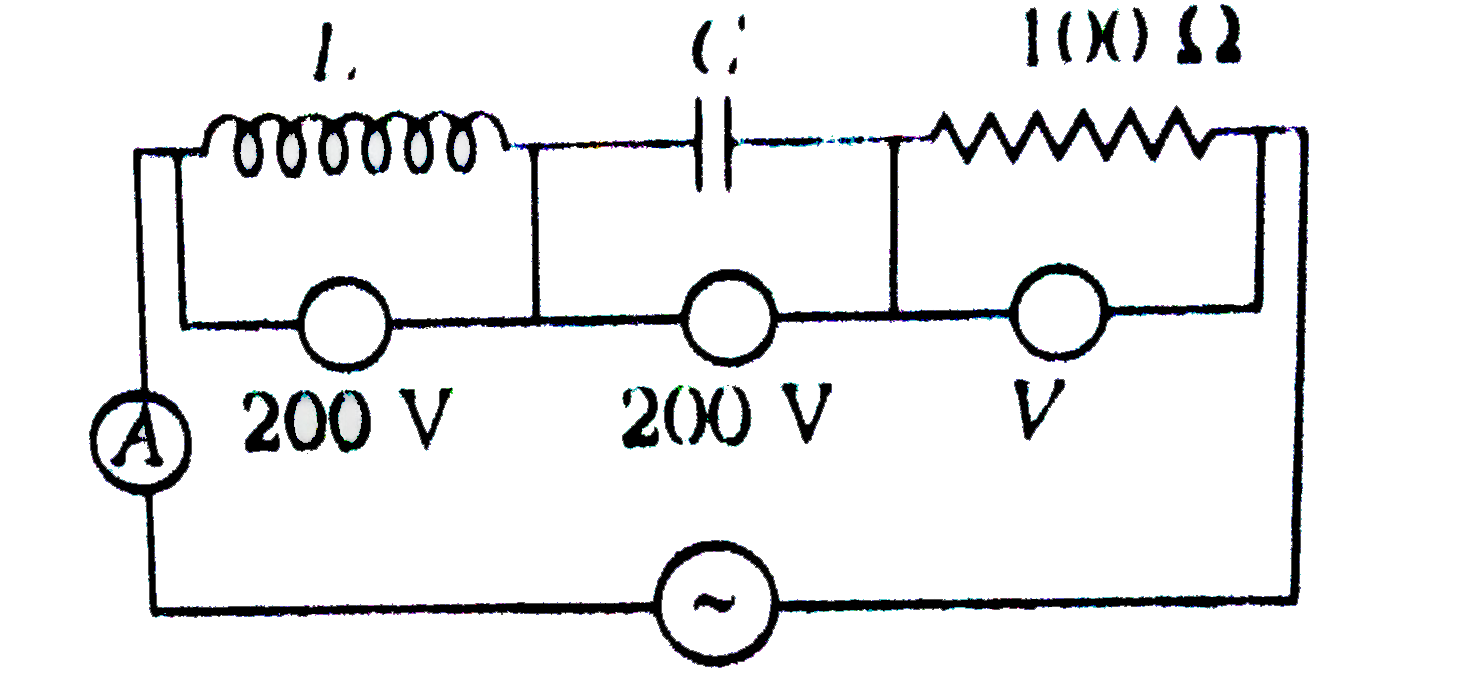
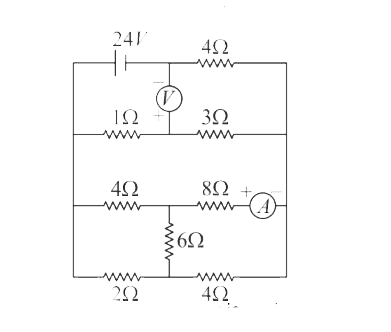
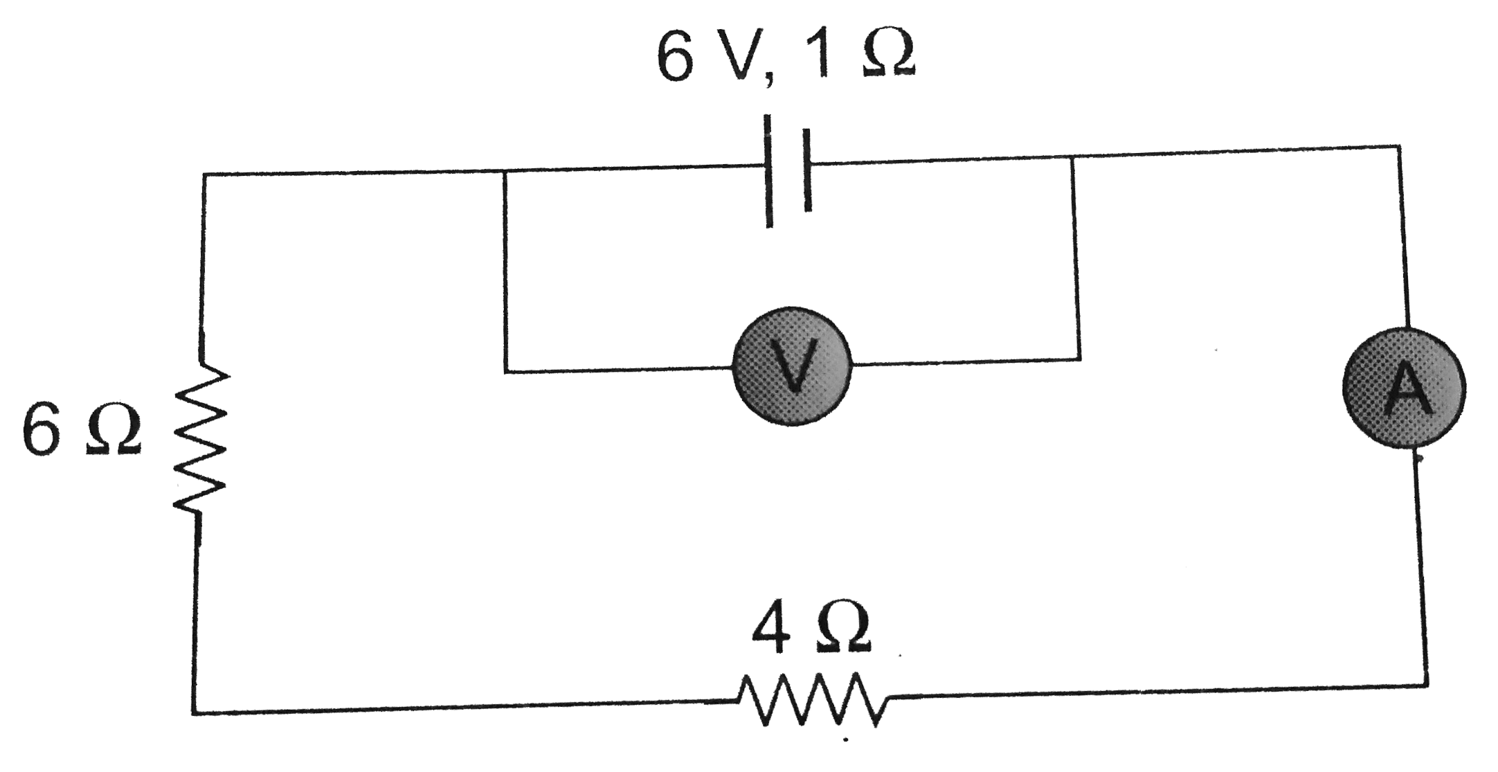
A ciruit to verify Ohm's law uses ammeter and voltmeter in series or parallel connected correctly to the resistor. In the circuit :
ammeter is always used in parallel and voltmeter is series
Both ammeter and voltmeter must be connected in parallel
ammeter is always connected in series and voltmeter in parallel
Both, ammeter and voltmeter must be connected in series
To solve the question regarding the connection of ammeter and voltmeter in a circuit designed to verify Ohm's law, we need to analyze the roles of each instrument in the circuit.
1. Understanding Ohm's Law:
Ohm's law states that the current (I) flowing through a conductor between two points is directly proportional to the voltage (V) across the two points, given by the formula V=I⋅R, where R is the resistance.
2. Circuit Components:
In the circuit, we have a battery (providing EMF), a resistor (whose resistance we want to measure), an ammeter (to measure current), and a voltmeter (to measure voltage).
3. Connection of the Ammeter:
The ammeter is designed to measure the current flowing through the circuit. For it to measure the current accurately, it must be connected in series with the resistor. This way, all the current flowing through the resistor also flows through the ammeter.
Conclusion: The ammeter is connected in series.
4. Connection of the Voltmeter:
The voltmeter measures the voltage across the resistor. To do this accurately, it must be connected in parallel with the resistor. This allows the voltmeter to measure the potential difference directly across the resistor without affecting the current flowing through the circuit.
Conclusion: The voltmeter is connected in parallel.
5. Final Verification:
- If the ammeter were connected in parallel, it would create a low-resistance path, causing most of the current to bypass the resistor, which would lead to incorrect current readings.
- If the voltmeter were connected in series, it would significantly increase the total resistance in the circuit, preventing current from flowing properly.
Final Answer:
- The ammeter is connected in series with the resistor.
- The voltmeter is connected in parallel with the resistor.
Ohm's law states that the current (I) flowing through a conductor between two points is directly proportional to the voltage (V) across the two points, given by the formula V=I⋅R, where R is the resistance.
In the circuit, we have a battery (providing EMF), a resistor (whose resistance we want to measure), an ammeter (to measure current), and a voltmeter (to measure voltage).
The ammeter is designed to measure the current flowing through the circuit. For it to measure the current accurately, it must be connected in series with the resistor. This way, all the current flowing through the resistor also flows through the ammeter.
The voltmeter measures the voltage across the resistor. To do this accurately, it must be connected in parallel with the resistor. This allows the voltmeter to measure the potential difference directly across the resistor without affecting the current flowing through the circuit.
- If the ammeter were connected in parallel, it would create a low-resistance path, causing most of the current to bypass the resistor, which would lead to incorrect current readings.
- If the voltmeter were connected in series, it would significantly increase the total resistance in the circuit, preventing current from flowing properly.
- The ammeter is connected in series with the resistor.
- The voltmeter is connected in parallel with the resistor.
Topper's Solved these Questions
Similar Questions
Why is ammeter connected in series and voltmeter in parallel in the circuit?
View SolutionThe reading of ammeter and voltmeter in the given circuit is
_PHY_E06_306_Q01.png)
View SolutionThe reading of ammeter and voltmeter in the following circuit are respectively

View SolutionIn the circuit shown, the battery, the ammeter and the voltmeter are ideal. Pick the correct choice(s) :

View SolutionBy mistake, a voltmeter is connected in series and an ammeter is connected in parallel, with a resistance in an electrical circuit. What will happen to the instruments?
View SolutionThree resistors of 5Ω,10Ωand15Ω are connected in series and the combination is connected to battery of 30 V. Ammeter and Voltmeter are connected in the circuit. Draw a circuit diagram to connect all the devices in proper correct order. What is the corrent flowing and potential difference across 10Ω resistance?
View SolutionWhen two identical cells are connected either in series or in parallel across a 4 ohm resistor, they send the same current through it. The internal resistance of the cell in ohm is
View SolutionIn the circuit shown in figure , if ammeter and voltmeter are ideal , then the power consumed in 9Ω resistor will be .

View SolutionA battery of emf 1.4V and internal resistance 2Ω is connected to a resistor of 100ω resistance through an ammeter. This resistance of the ammeter is 4/3Ω. A voltmeter has also been connected to find the potential difference across the resistor.
a. Draw the circuit diagram.
b. The ammeter reads 0.02A. What is the resistance of the voltmeter?
c. The voltmeter reads 1.1V. What is the error in the reading?
View SolutionIn the circuit shown here, the readings of the ammeter and voltmeter are

View Solution