In the circuit shown in figure , if ammeter and voltmeter are ideal , then the power consumed in 9Ω resistor will be .

3.33W
4W
1.44W
500W
The correct Answer is:B
Step by step video & image solution for In the circuit shown in figure , if ammeter and voltmeter are ideal , then the power consumed in 9 Omega resistor will be . by Physics experts to help you in doubts & scoring excellent marks in Class 12 exams.
Updated on:21/07/2023Similar Questions
In the circuit shown in figure, reading of ammeter will
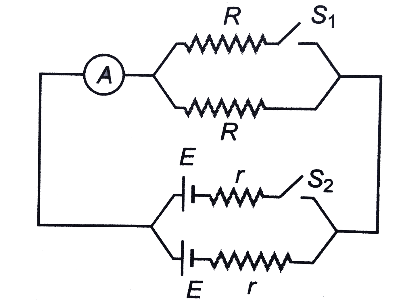
View SolutionIn the circuit shown here, the readings of the ammeter and voltmeter are
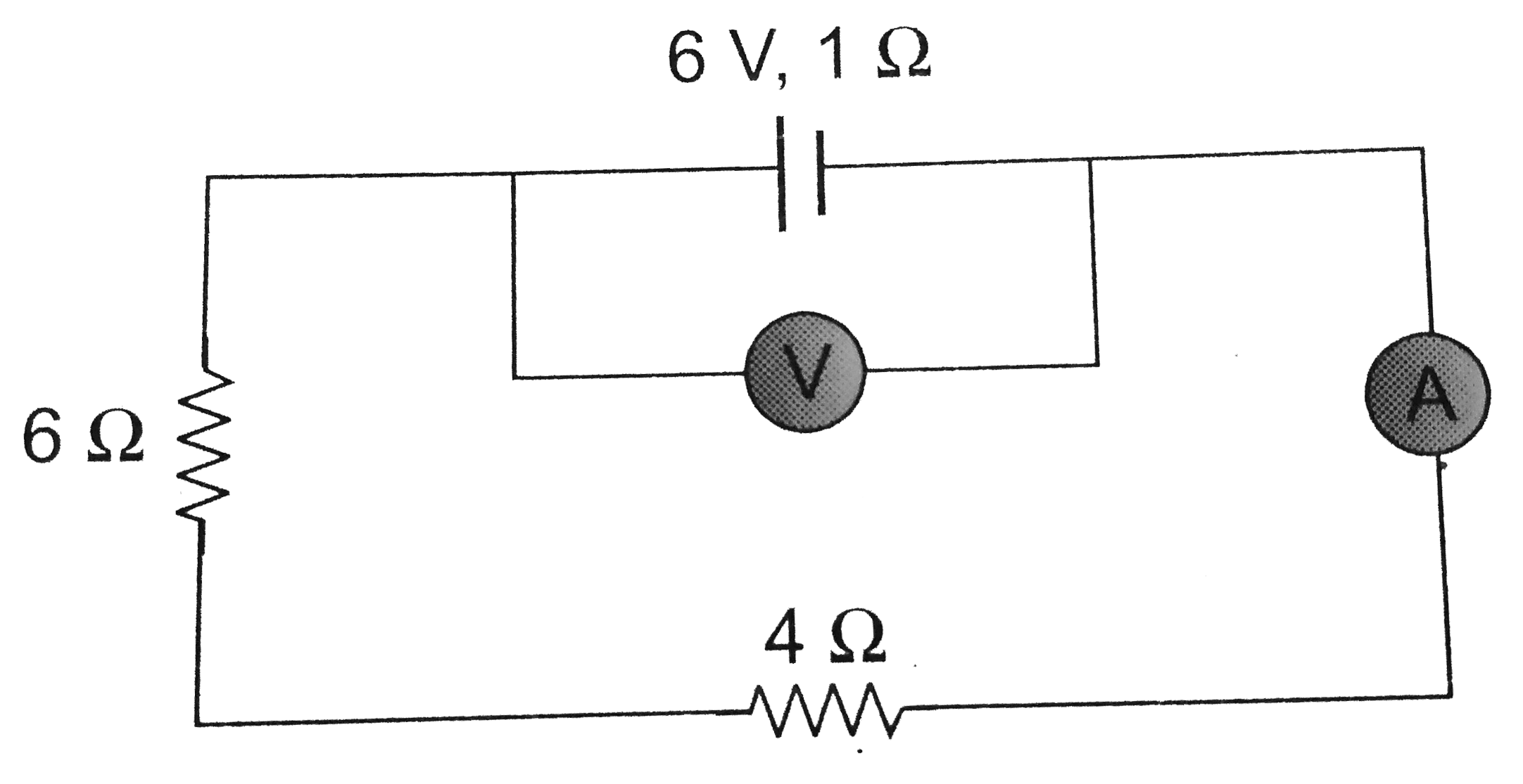
View SolutionIn the circuit shown in the figure, the voltmeter reading is
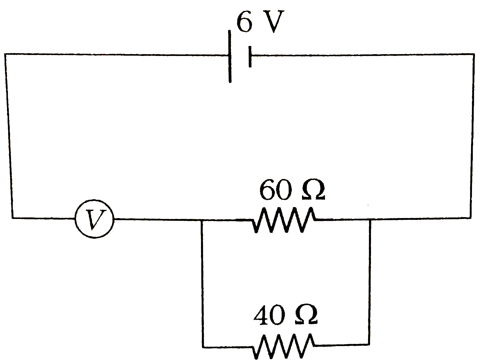
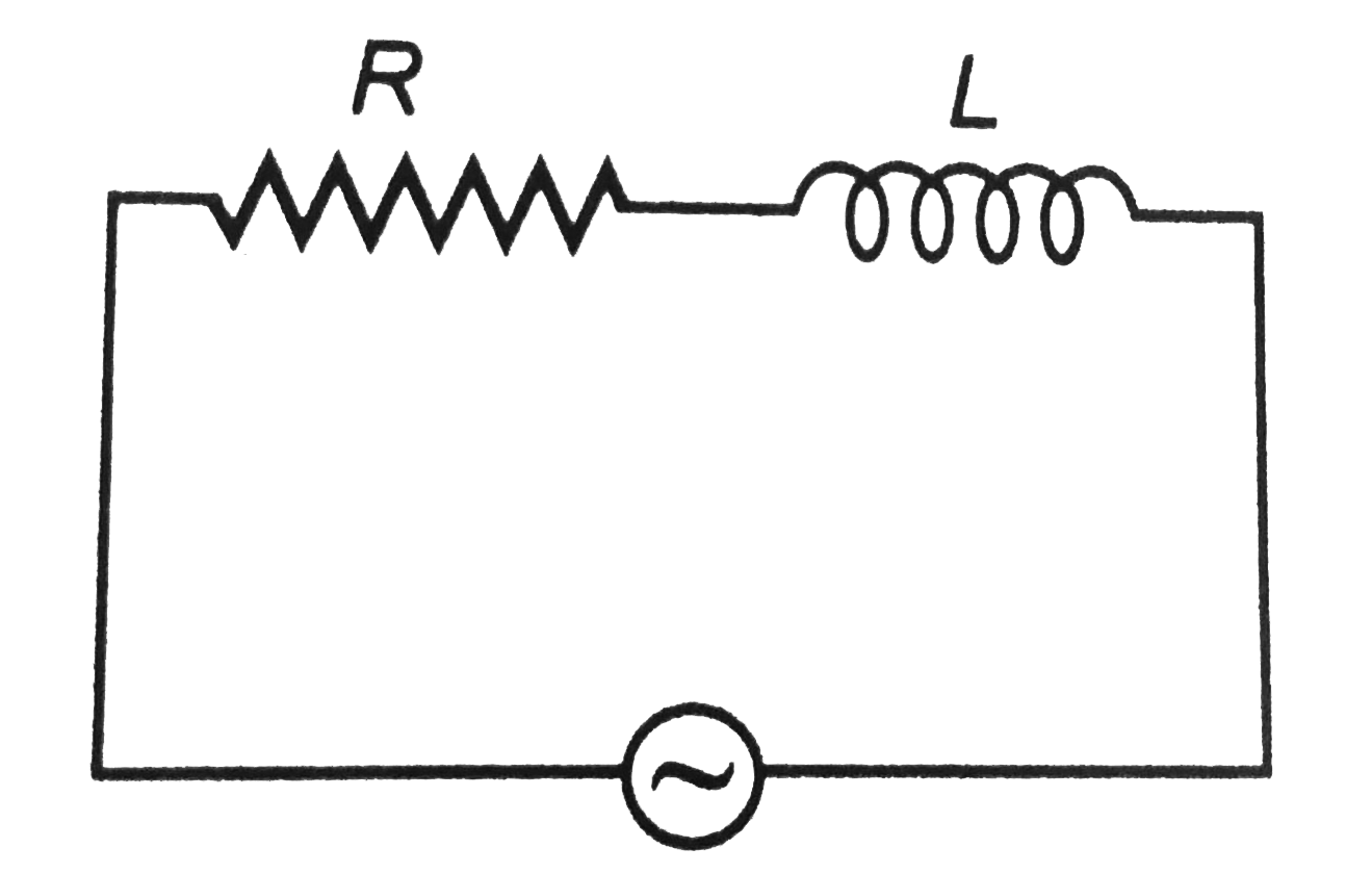
View SolutionIn the circuit shown in figure, the power consumed is
 .
.
View SolutionIn the circuit shown in figure, what will be the readings of voltmeter and ammeter?
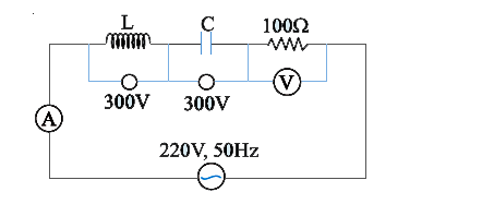
View SolutionIn the circuit shown, the battery, the ammeter and the voltmeter are ideal. Pick the correct choice(s) :
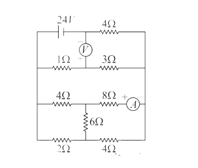
View Solution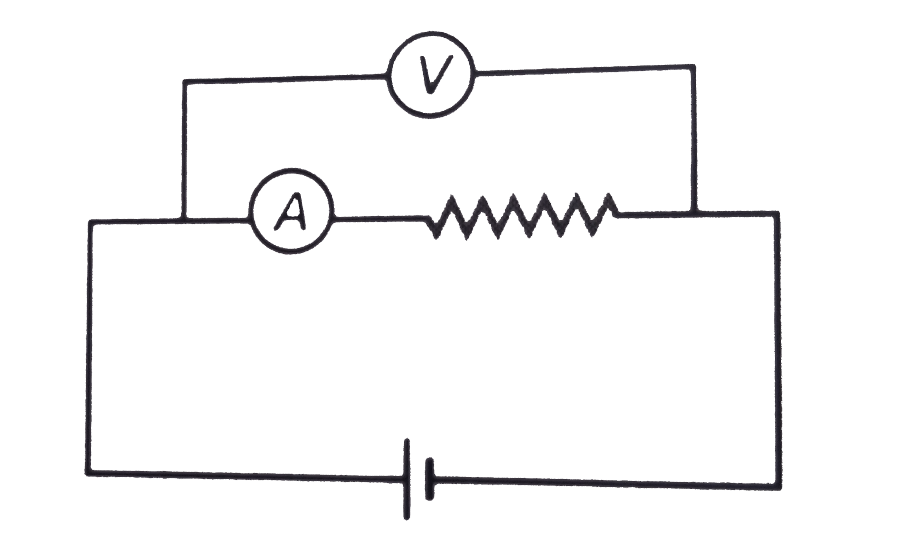
Assertion : In the circuit shown in figure ammeter and voltmeter are non-ideal when positions of ammeter and voltmeter are changed, reading of ammeter will increase while of voltmeter will decrease.
Reason : Resistance of an ideal ammeter is zero while that of an ideal voltmeter is infinite.
View SolutionIn the circuit shown in the figure , the resistance marked R can be varied by using a Rheostat. The power across the 5 Omega resistor will be maximum if the Rhoestat has resistance equal to
_PHY_E01_015_Q01.png)
View SolutionIn the circuit shown in figure ammeter and voltmeter are ideal. If E=4V,R=9Ω and r=1Ω then readings of ammeter and voltmeter are
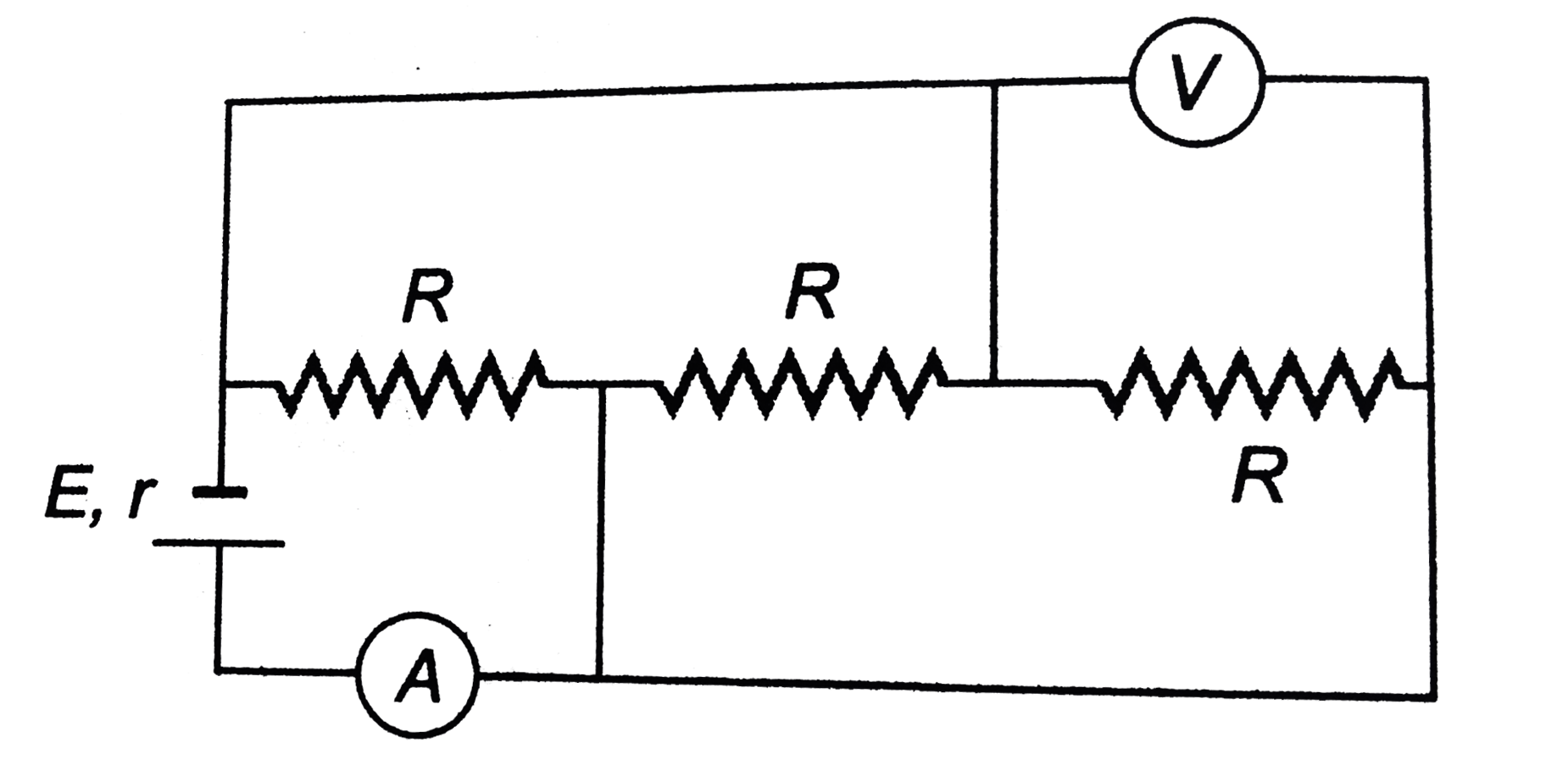
View SolutionIn the circuit shown in figure ammeter and voltmeter are ideal. If E=4V,R=9Ω and r=1Ω then readings of ammeter and voltmeter are

View Solution
