Resistance of a milli ammeter is R1 of an ammeter is R2 of a voltmeter is R3 and of a kilovoltmeter is R4. Find the correct order of R1,R2,R3 and R4.
To determine the correct order of resistances R1 (milliammeter), R2 (ammeter), R3 (voltmeter), and R4 (kilovoltmeter), we can analyze the function and construction of each device.
Step 1: Analyze the milliammeter and ammeter
- A milliammeter is designed to measure small currents and has a relatively low resistance R1.
- An ammeter, which measures larger currents, typically has a slightly higher resistance R2 than a milliammeter because it is designed to handle larger current ranges.
Relation:
R1<R2
Step 2: Analyze the voltmeter and kilovoltmeter
- A voltmeter is used to measure voltage and has a high resistance R3 to minimize the current drawn from the circuit.
- A kilovoltmeter is a specialized voltmeter that can measure high voltages and therefore has an even higher resistance R4.
Relation:
R3<R4
Step 3: Compare the resistances of ammeter and voltmeter
- The resistance of an ammeter R2 is generally lower than that of a voltmeter R3 because ammeters are designed to allow current to flow through them with minimal resistance.
Relation:
R2<R3
Step 4: Combine the relations
From the above steps, we have:
1. R1<R2
2. R2<R3
3. R3<R4
Combining these inequalities gives us the overall order:
R1<R2<R3<R4
Final Order
The correct order of resistances is:
R1<R2<R3<R4
---
- A milliammeter is designed to measure small currents and has a relatively low resistance R1.
- An ammeter, which measures larger currents, typically has a slightly higher resistance R2 than a milliammeter because it is designed to handle larger current ranges.
R1<R2
- A voltmeter is used to measure voltage and has a high resistance R3 to minimize the current drawn from the circuit.
- A kilovoltmeter is a specialized voltmeter that can measure high voltages and therefore has an even higher resistance R4.
R3<R4
- The resistance of an ammeter R2 is generally lower than that of a voltmeter R3 because ammeters are designed to allow current to flow through them with minimal resistance.
R2<R3
From the above steps, we have:
1. R1<R2
2. R2<R3
3. R3<R4
R1<R2<R3<R4
The correct order of resistances is:
R1<R2<R3<R4
Topper's Solved these Questions
- CURRENT ELECTRICITYBOOK - DC PANDEY ENGLISHCHAPTER - CURRENT ELECTRICITYEXERCISE - Example Type 1
2 Videos
- CURRENT ELECTRICITYBOOK - DC PANDEY ENGLISHCHAPTER - CURRENT ELECTRICITYEXERCISE - Example Type 2
1 Videos
- COMMUNICATION SYSTEMBOOK - DC PANDEY ENGLISHCHAPTER - COMMUNICATION SYSTEMEXERCISE - Subjective
11 Videos
- ELECTROMAGNETIC INDUCTIONBOOK - DC PANDEY ENGLISHCHAPTER - ELECTROMAGNETIC INDUCTIONEXERCISE - Medical entrances gallery
25 Videos
Similar Questions
A voltmeter of resistance R1 and an ammeter of resistance R2 are connected in series across a battery oif negligible internal resistance. When as resistance R is connected in parallel to voltmeter reading of ammeter increases three times white that of voltmeter reduces to one third. Find the ratio of R1 and R2.
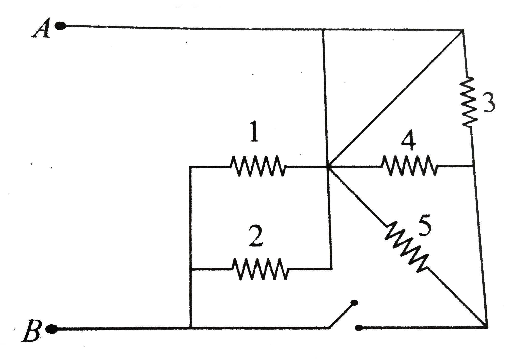
View SolutionThe circuit has resistors of equal resistance R. The equivalent resistance between A and B, when key is closed is R1 and when key is open is R2. Find the ratio R1andR2 .
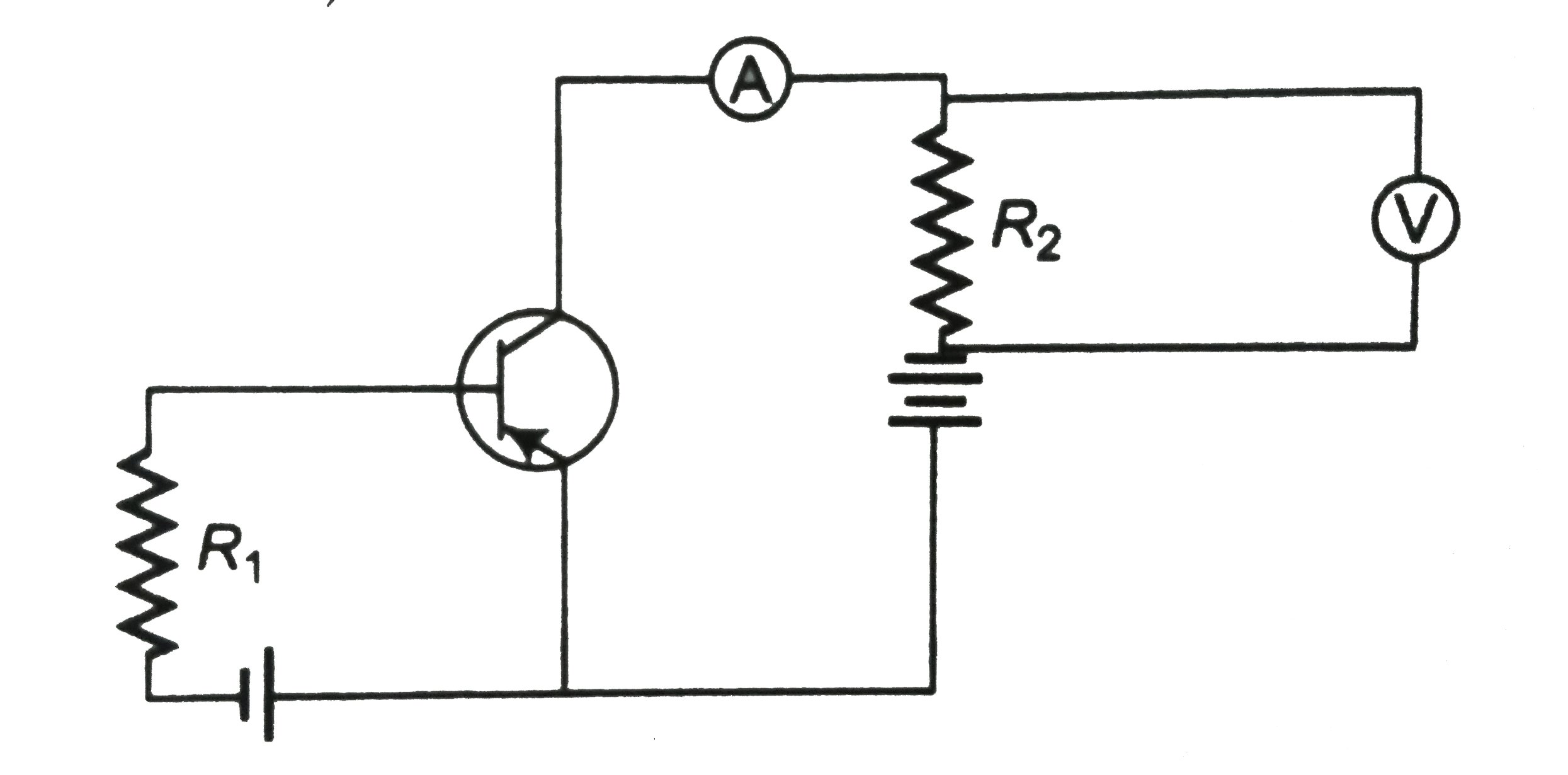
View SolutionIf the resistance R1 is increased , how will the readings of the ammeter and voltmeter change?
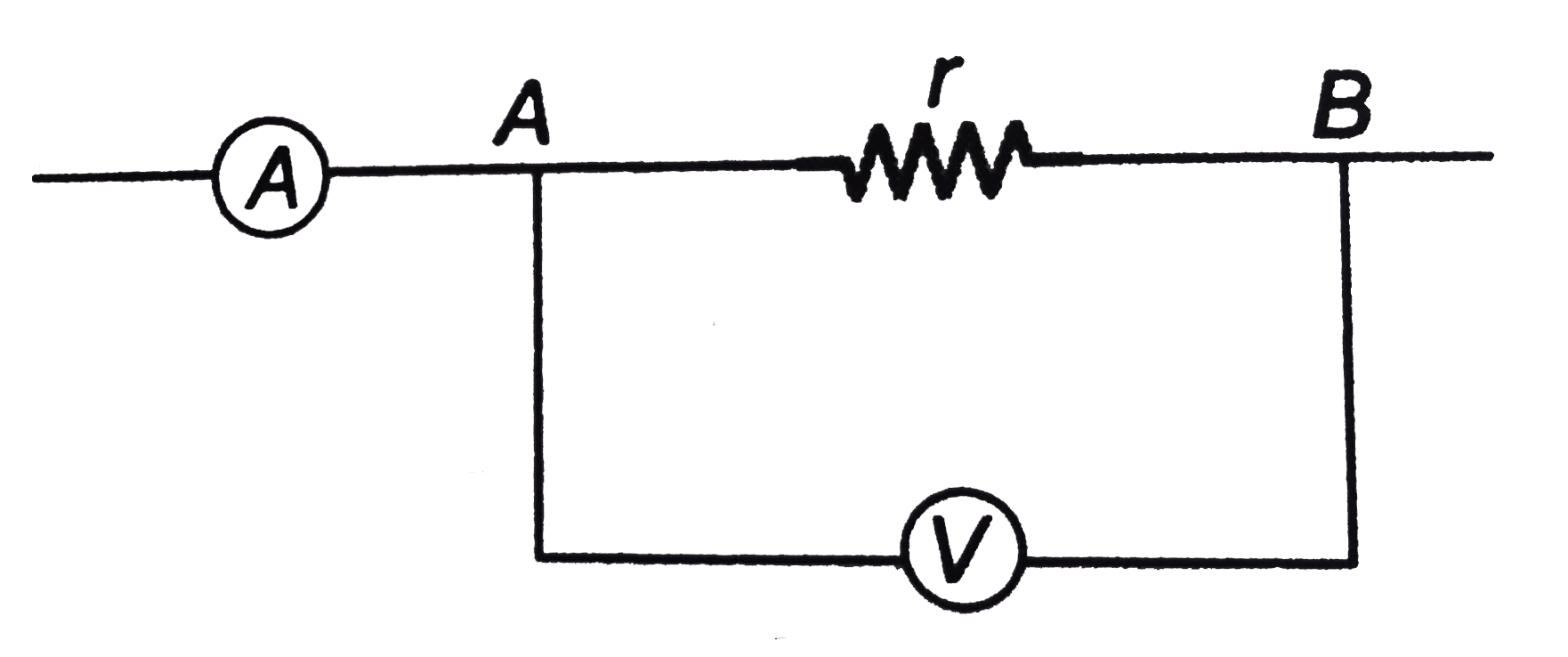
View SolutionDetermine the resistance r if an ammeter shows a current of I=5A and a voltmeter 100V. The internal resistance of the voltmeter is R=2,500Ω
View SolutionA Candidate connects a moving coil ammeter A and a moving coil voltmeter V and a resistance R as shown figure
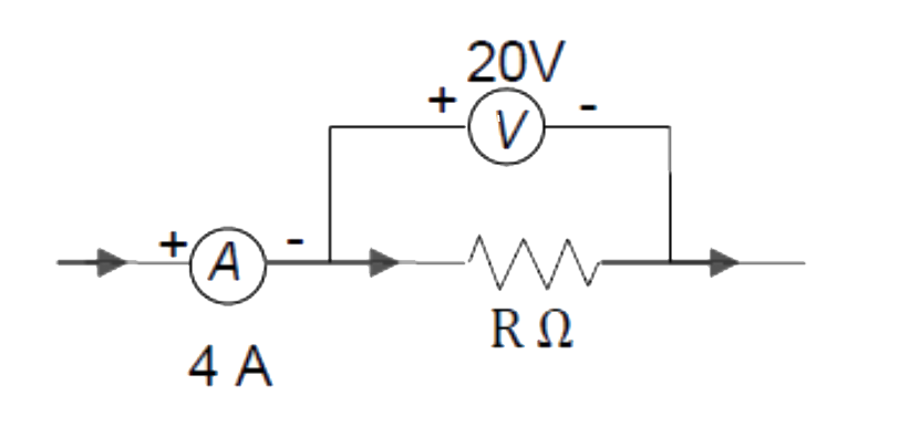
If the voltmeter reads 20 V and the ammeter reads 4 A , then R is
View Solutionr+r3+r1−r2=
View SolutionThe power dissipated in resistor R3 shown in the figure is 15 W. The reading the ammeter is 500 mA and the reading of the voltmeter is 10 V. Ammeter, voltmeter and battery are ideal.
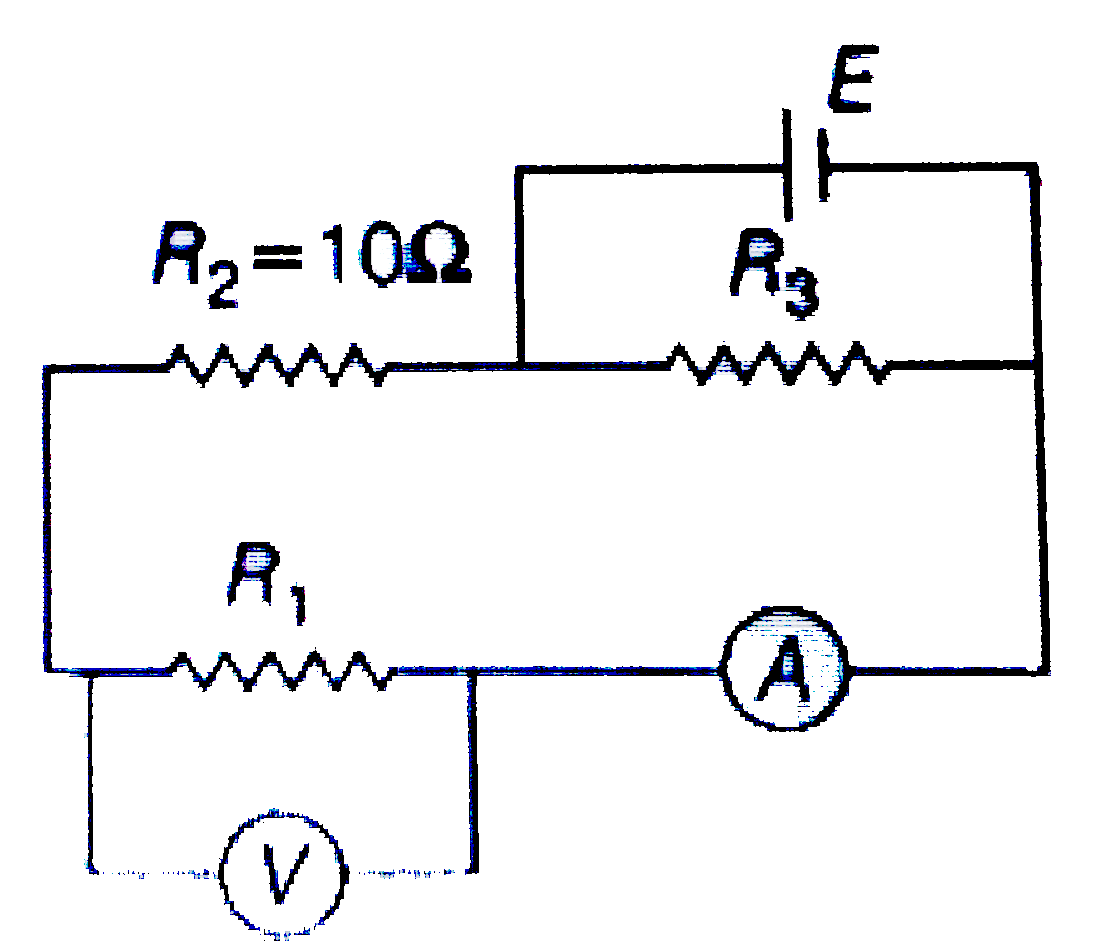
Find the resistance R1
View SolutionThe power dissipated in resistor R3 shown in the figure is 15 W. The reading the ammeter is 500 mA and the reading of the voltmeter is 10 V. Ammeter, voltmeter and battery are ideal.
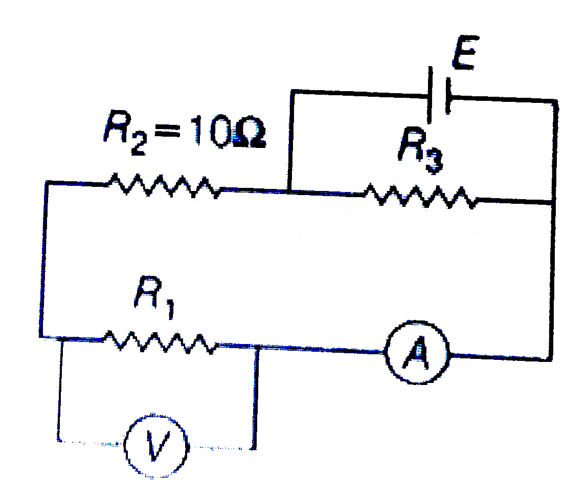
Find the resistance R3
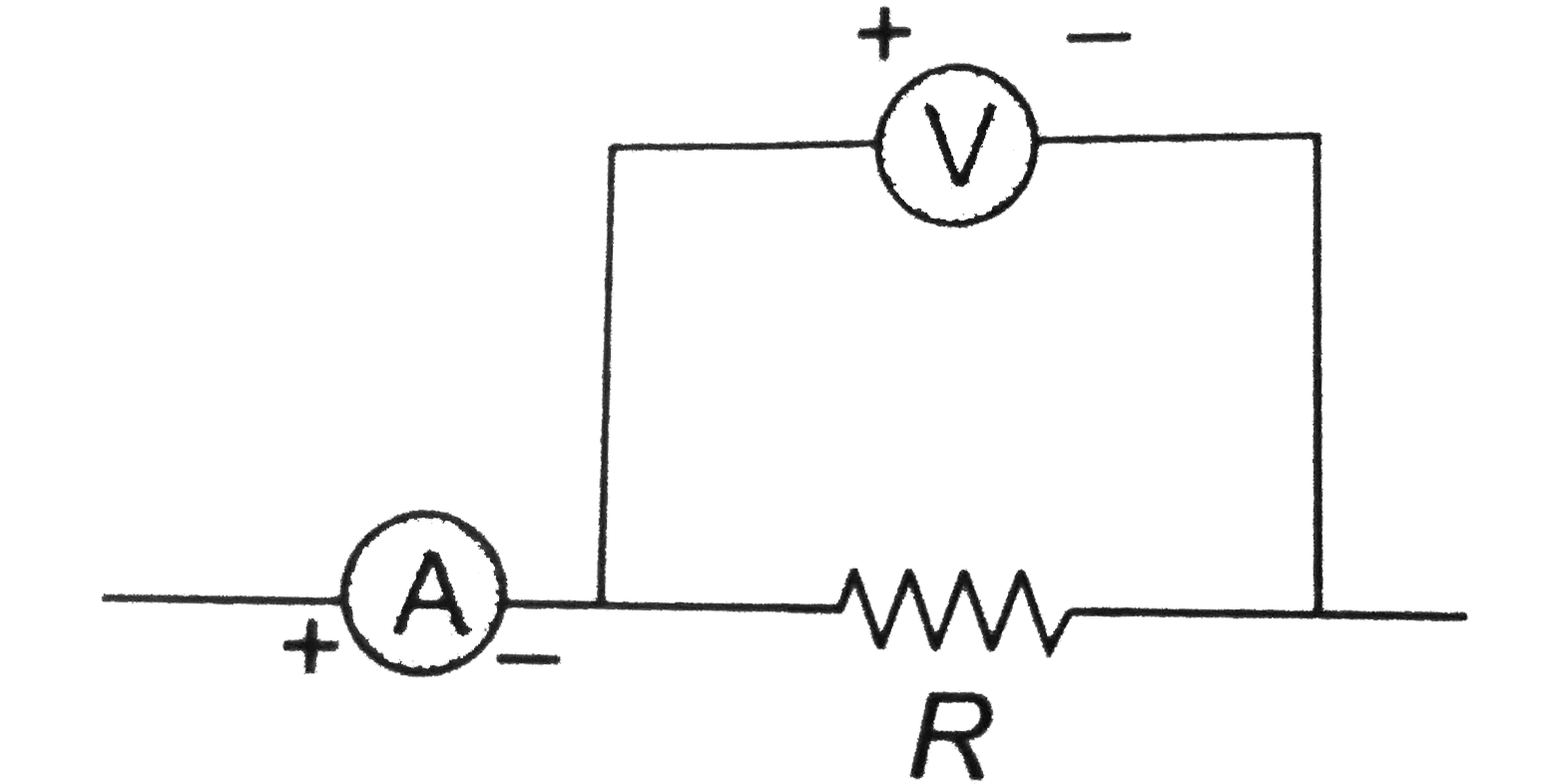
View SolutionA candidate connects a moving coil voltmeter V, a moving coil ammeter A and a resistance R as shown in figure. If the voltmeter reads 24V and the ammeter reads 4A, R is
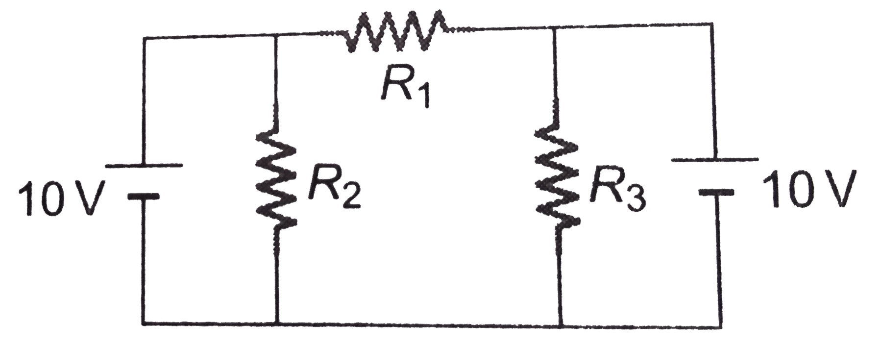
View SolutionIn the curcuit shown in figure R1=R2=R3=10Ω. Find the currents through R1 and R2
View Solution
