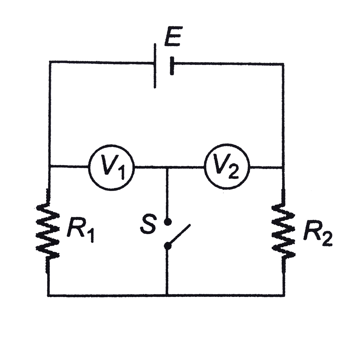
In the circuit shownin figure V1 and V2 are two voltmeter of resistances 3000Ω and 2000Ω respectively. In additions R1=2000Ω, R2=3000ω and E=200V then
a. Fid the reading of voltmeters V1 and V2 when
i. switch S is open
ii. Switch S is closed
b. Current through S, when it is closed (Disregard the resistance of battery)
The correct Answer is:A, B
a. i. When switch S is open V1andV2 are in series, connected to 200V battery. Potential will drop in direct ratio of their resitors.
∴V1:V2=RV1:RV2=3000:2000
=3:2
∴V1=35×200=120V
V2=25×200=80V
ii. When S is closed then V1 and R1 are in parallel.Similarly, V2 and R2 are also in parallel. Now, they are in series and they come out to be equal. So 200V will equalilty distribute between them.
∴V1=V2=2002=100V each
b. i2=1002000=120A
i4=1003000=130A

If we apply junction law at P then current through switch
=i2−i=160A in upward direction.
Topper's Solved these Questions
- BOOK - DC PANDEY ENGLISHCHAPTER - CURRENT ELECTRICITYEXERCISE - Level 2 Single Correct26videos
CURRENT ELECTRICITY
- BOOK - DC PANDEY ENGLISHCHAPTER - CURRENT ELECTRICITYEXERCISE - Level 2 More Than One Correct10videos
CURRENT ELECTRICITY
- BOOK - DC PANDEY ENGLISHCHAPTER - CURRENT ELECTRICITYEXERCISE - OBJECTIVE_TYPE1videos
CURRENT ELECTRICITY
- BOOK - DC PANDEY ENGLISHCHAPTER - COMMUNICATION SYSTEMEXERCISE - Subjective11videos
COMMUNICATION SYSTEM
- BOOK - DC PANDEY ENGLISHCHAPTER - ELECTROMAGNETIC INDUCTIONEXERCISE - Medical entrances gallery25videos
ELECTROMAGNETIC INDUCTION
Similar Questions
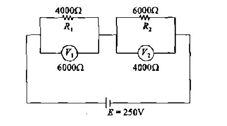
In the circuit shown in figure-3.391, V1andV2 are two voltmeters having resistances 6000Ωand4000Ω respectively EMF of battery is 250V, having negligible internal resistance. Two resistances R1andR2 are 4000Ωand6000Ω respectively. Find the reading of the voltamter V1andV2 when
(a) Switch S is open ltbgt (b) Switch S is closed
 View Solution
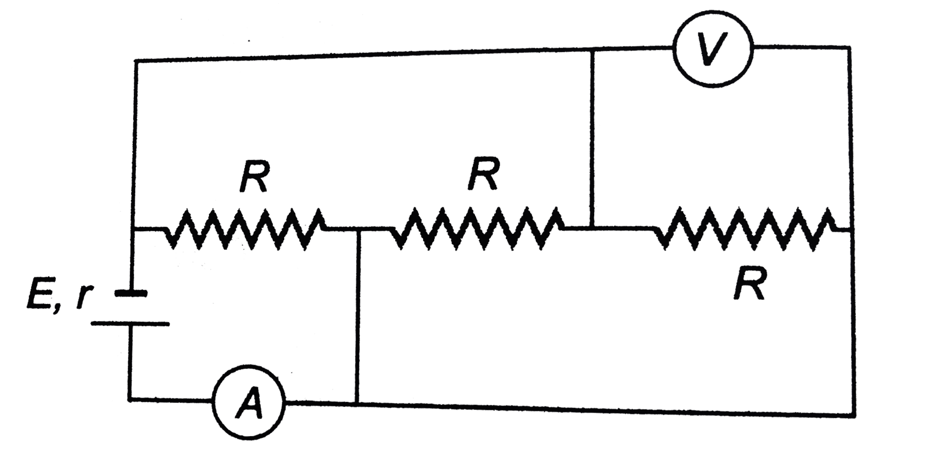
In the circuit shown in figure ammeter and voltmeter are ideal. If E=4V,R=9Ω and r=1Ω then readings of ammeter and voltmeter are
 View Solution
In the circuit shown in figure ammeter and voltmeter are ideal. If E=4V,R=9Ω and r=1Ω then readings of ammeter and voltmeter are
 View Solution
In the ciruit the cells E1andE2 have emfs of 4V and 8V and internal resistance 0.5Ωand1.0Ω, respectively. Calculate the current through 6Ω resistance.
 View Solution
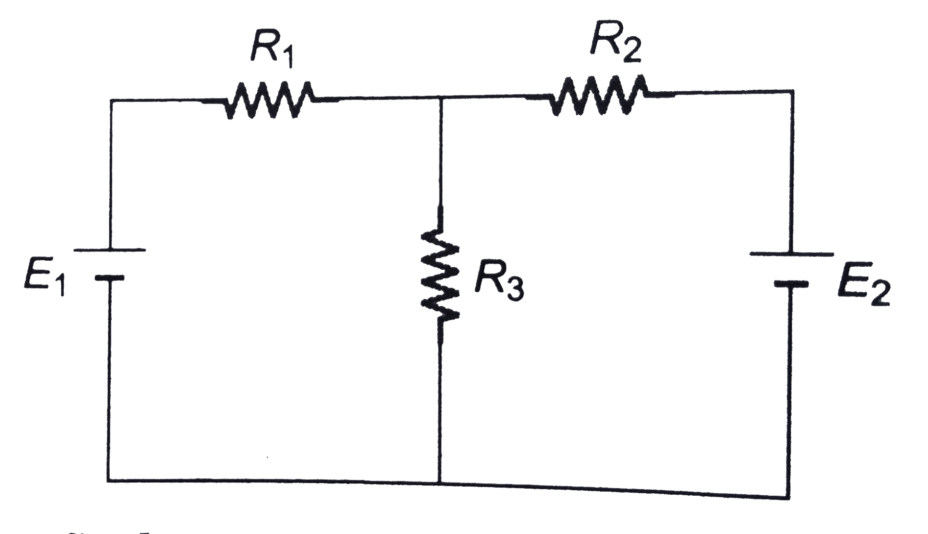
In the circuit shown in figure E1=7V,E2=1V,R1=2Ω,R2=2Ω and R3=3Ω respectively. Find the power supplied by the two batteries.
 View Solution
A voltmeter has resistance 2000Ω and range 5 V. For increasing its range upto 20V, a resistance of
View SolutionThe voltmeter shown in the figure reads 10V across 40 ω . The resistance of voltmeter is
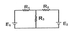
View SolutionIn the circuit shown, E1=7V,E2=7V,R1=R2=1Ω and R3=3Ω respectively. The current through the resistance R3
 View Solution
In the circuit shown, E1=7V,E2=7V,R1=R2=1Ω and R3=3Ω respectively. The current through the resistance R3
 View Solution
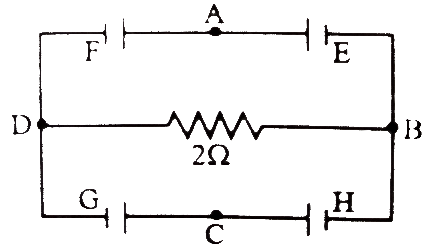
In the circuit shown E,F,G and H are cells of emf 2V,1V,3V and 1V respectively and their internal resistance are 2Ω,1Ω,3Ω and 1Ω respectively.
 View Solution

