Find the potential difference between points M and N of the system shown in figure, if the emf is equal to E=110V and the capacitance ratio C1C2is2.
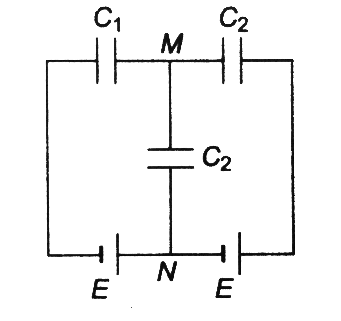
The correct Answer is:A, C
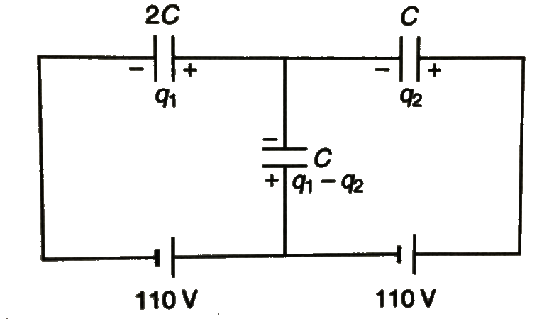
Applying loop law in two closed loops, we have
110−q2C+q1−q2C= or q2=(110C)
and −110+q12C+q1−q2C=0
orq1=(440C3)
potential difference between points M and N is
VN−Vm=q1−q2C
=1103 volt
Topper's Solved these Questions
- CAPACITORSBOOK - DC PANDEY ENGLISHCHAPTER - CAPACITORSEXERCISE - OBJECTIVE_TYPE
1 Videos
- CAPACITORSBOOK - DC PANDEY ENGLISHCHAPTER - CAPACITORSEXERCISE - OBJECTIVE_TYPE
1 Videos
- ATOMSBOOK - DC PANDEY ENGLISHCHAPTER - ATOMSEXERCISE - MEDICAL ENTRANCES GALLERY
42 Videos
- COMMUNICATION SYSTEMBOOK - DC PANDEY ENGLISHCHAPTER - COMMUNICATION SYSTEMEXERCISE - Subjective
11 Videos
Similar Questions
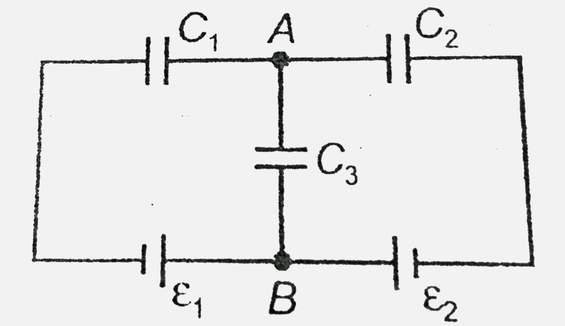
Find the potential difference VA−VB between points A and B of the circuit shown in figure.
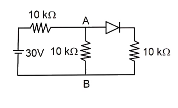
View SolutionFind the potential difference between A and B as shown in the figure
View SolutionFind the potential difference Va−Vb between the points a and b shown in each part of the figure.
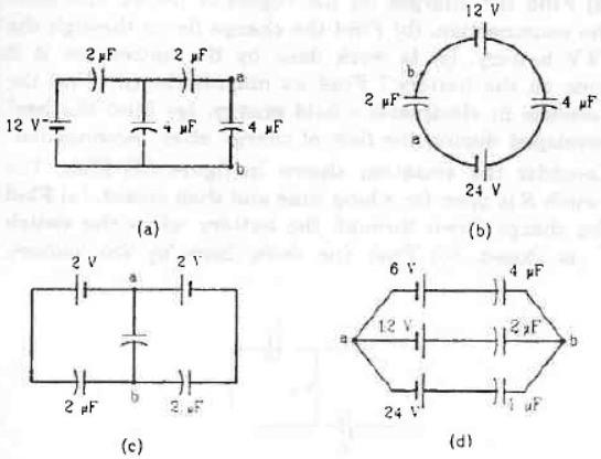
View SolutionFind the potential difference Va−Vb , between the points a and b shown in each part of the figure.

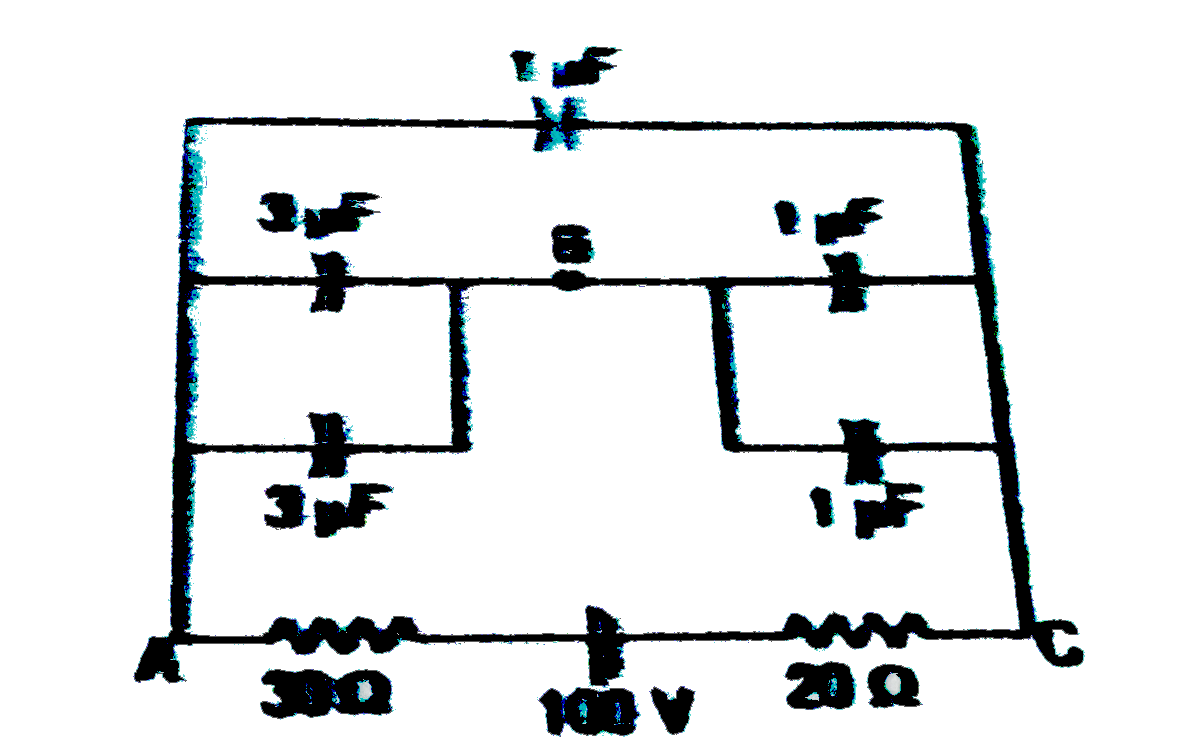
View Solutionfind the potential difference between th point A and B and between the point B and C of figure in steady state.
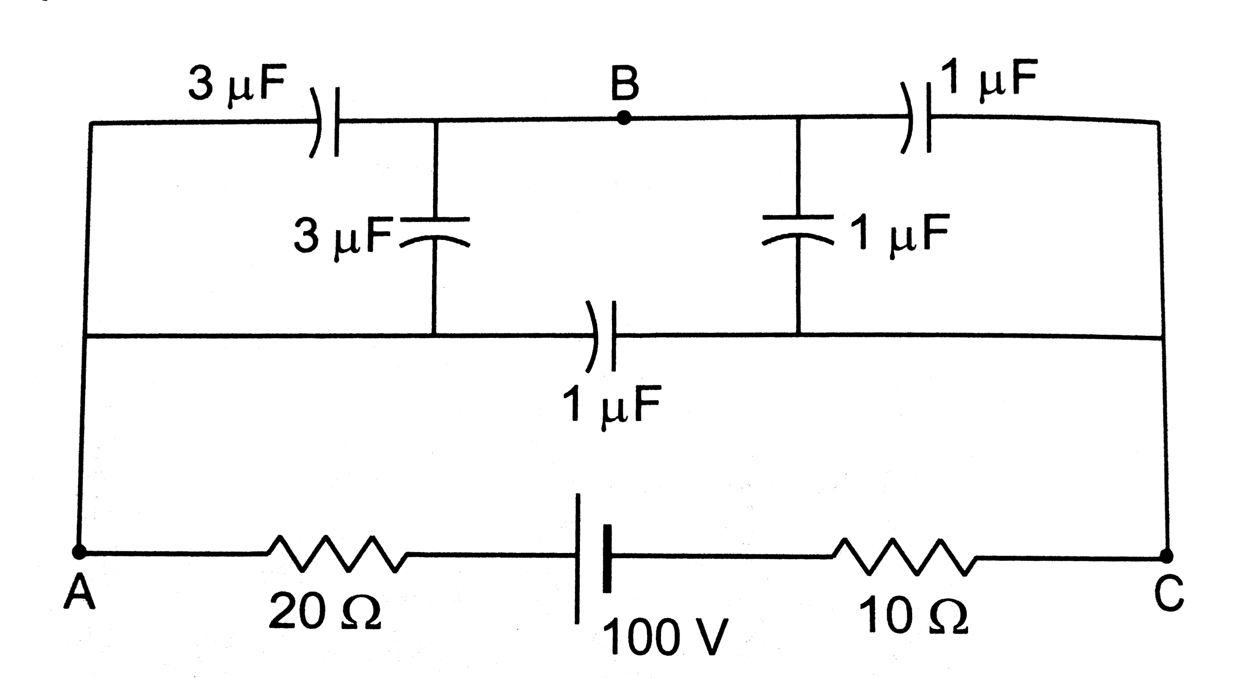
View SolutionFind the potential difference between the points A and B and between the points B ans C of figure in steady state.
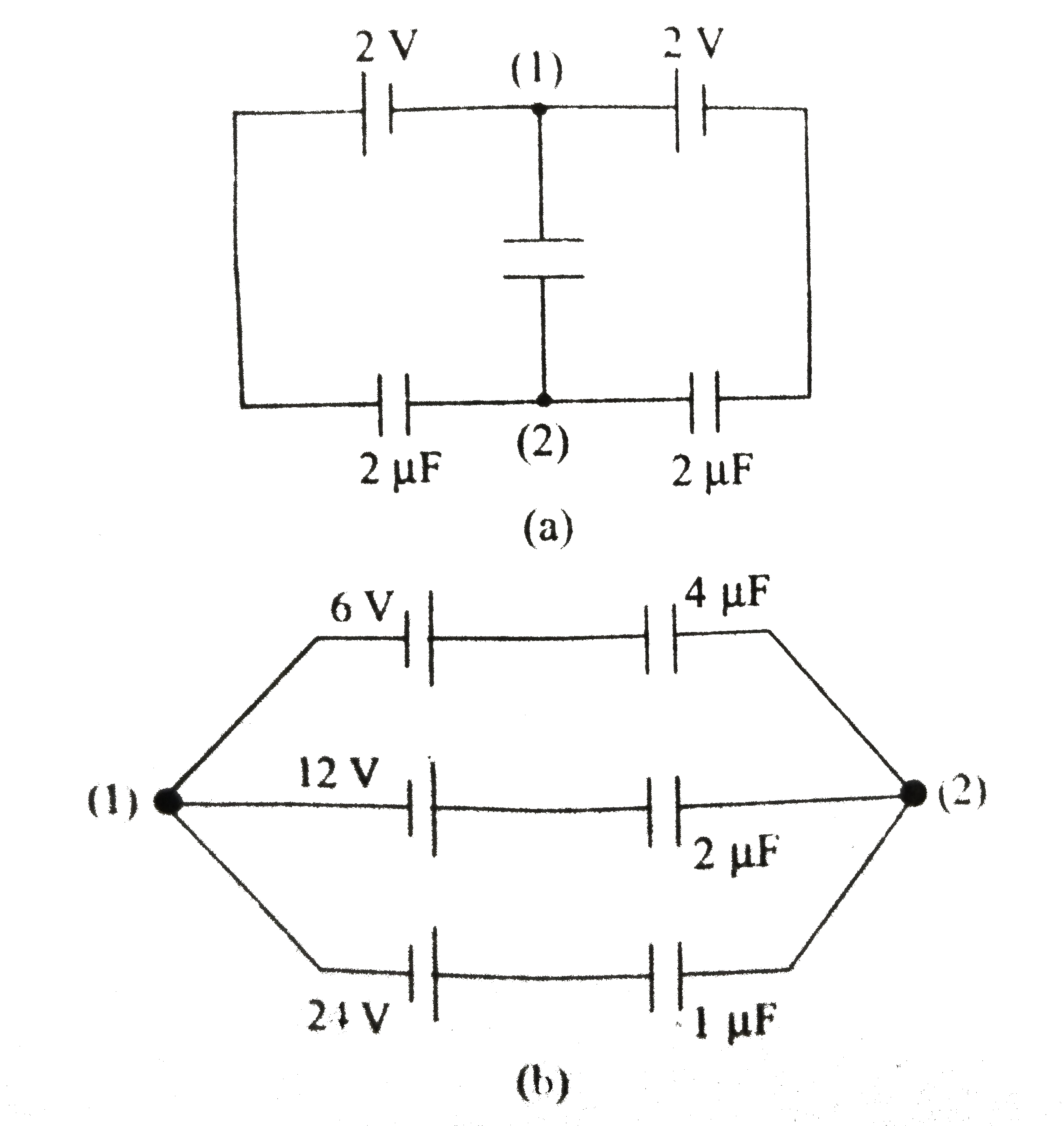
View SolutionFind the potential difference Va−Vb between the points (1) and (2) shown in each part of Fig.
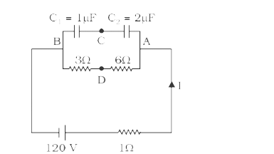
View SolutionAt steady state, the potential difference between points C and D in the circuit shown is equal to ________ V.
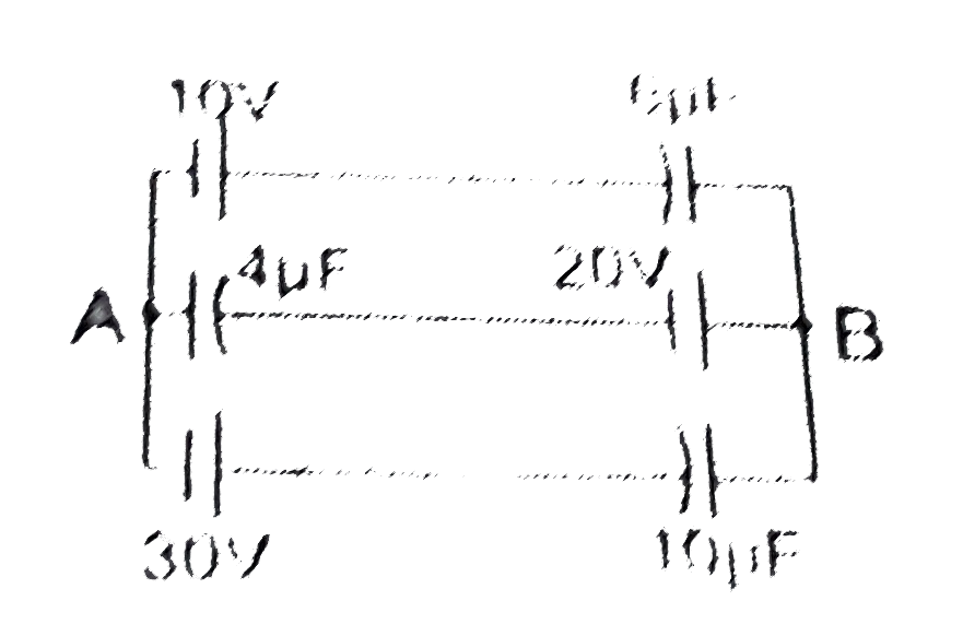
View SolutionFind the potential difference between the points A and B (VA−VB) as shown in figure. (Initially all the capacitors are uncharged)
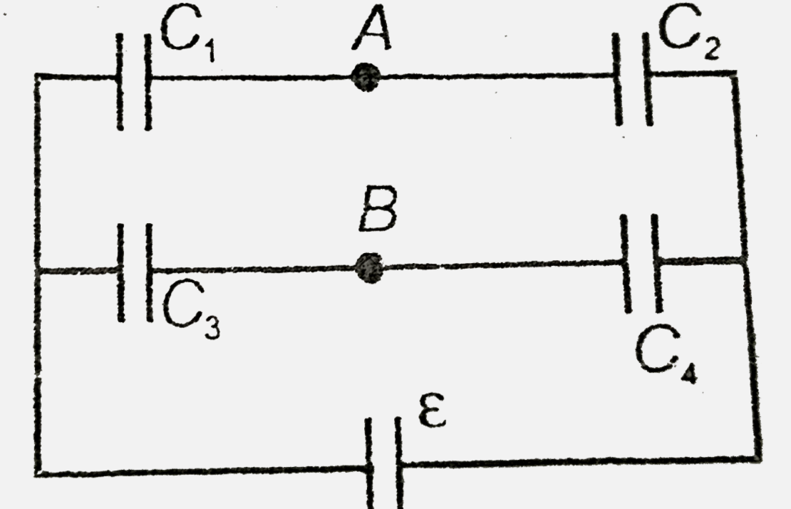
View SolutionDetermine the potential difference VA−VB between point A and B of the circuit shown in figure . Under what condition is it equal to zero ?
View Solution
