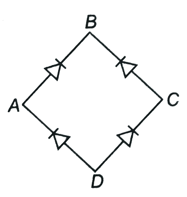
In figure the input is across the terminals A and C and the output is across B and D. Then the output is
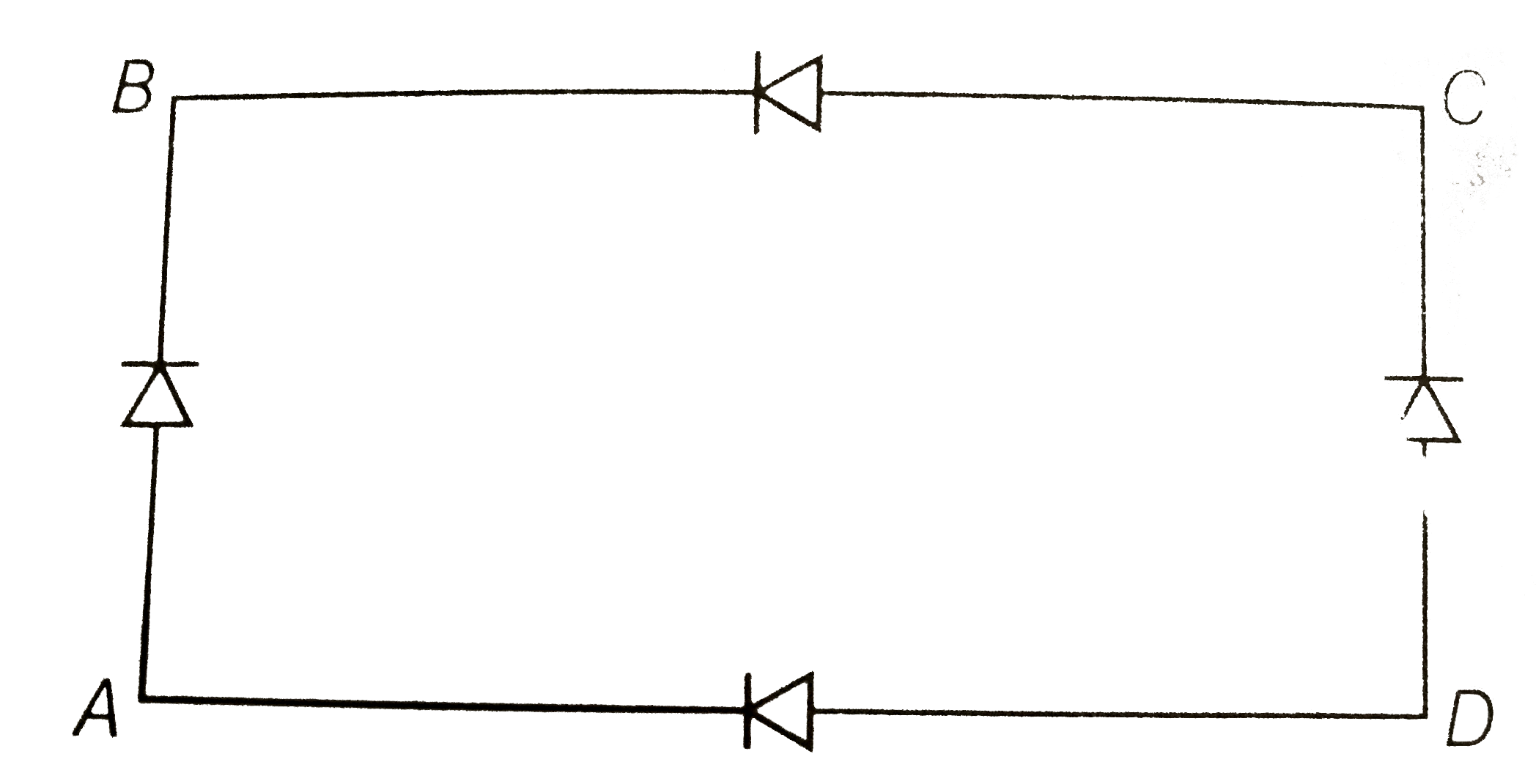
The correct Answer is:A
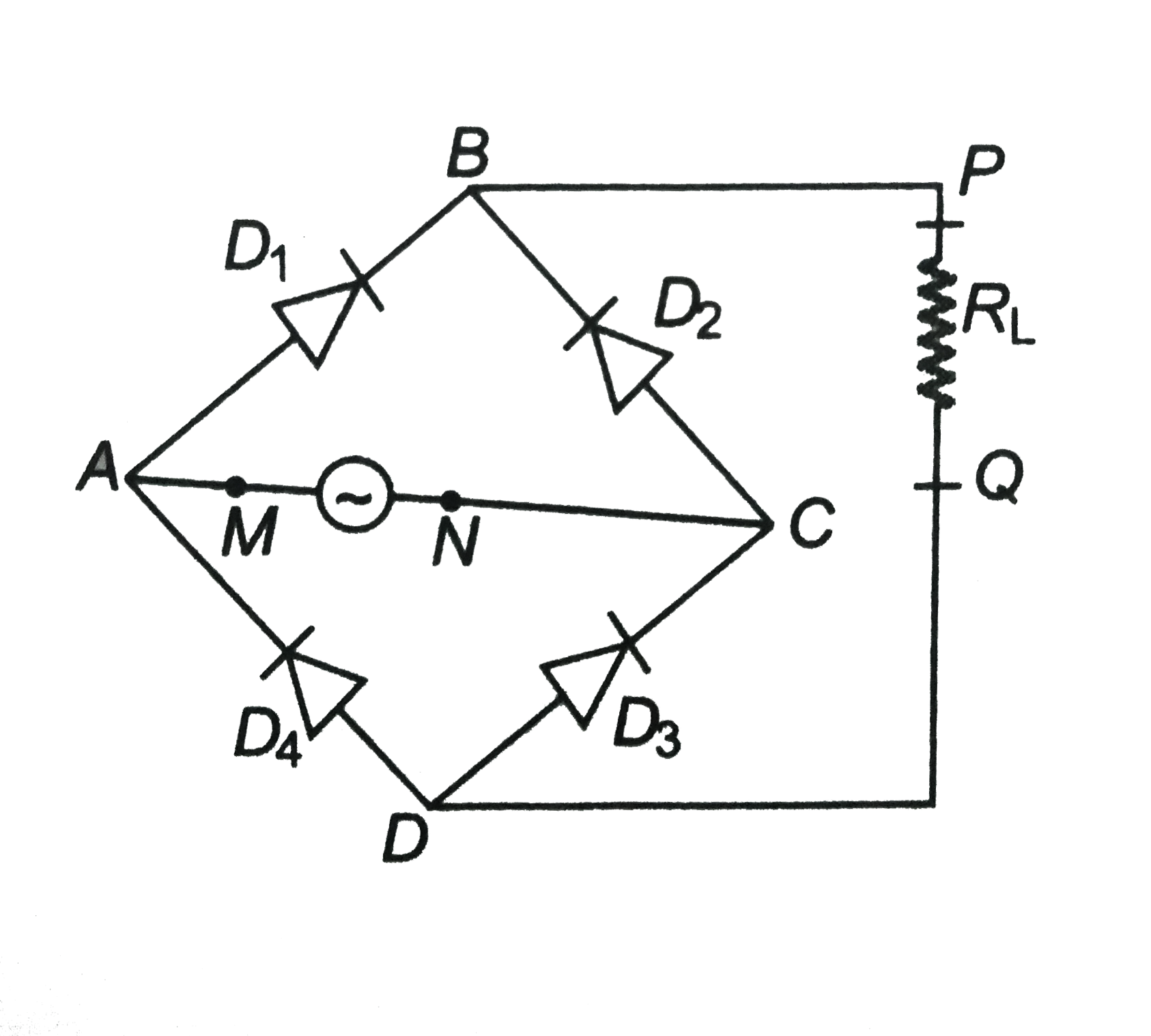
( c ) During the half cycle when VM>VN,D1andD1 are forward
biased. Hence , the path of current is MABPQDCNM.
In the second half cycle, when VN>VM,D2andD4 are forward
biased while D1 and D3 are reverse biased. Hence , the path of
current is NCBPQDAMN .
Therefore, in both half cycles current flows from P to Q from load
resistance RL . Or , it is a full - wave rectifier .
 .
.
Topper's Solved these Questions
- SEMICONDUCTORSBOOK - DC PANDEY ENGLISHCHAPTER - SEMICONDUCTORSEXERCISE - Solved Example
14 Videos
- SEMICONDUCTORSBOOK - DC PANDEY ENGLISHCHAPTER - SEMICONDUCTORSEXERCISE - Exercise35.1
1 Videos
- REFRACTION OF LIGHTBOOK - DC PANDEY ENGLISHCHAPTER - REFRACTION OF LIGHTEXERCISE - Level 2 Subjective
21 Videos
- SOLVED PAPER 2017BOOK - DC PANDEY ENGLISHCHAPTER - SOLVED PAPER 2017EXERCISE - Solved papers 2017(JIPMER)
32 Videos
Similar Questions
Knowledge Check
The following figure shows a logic gate circuit with two inputs A and B and the output Y. The voltage waveforms of A,B and Y are as given :
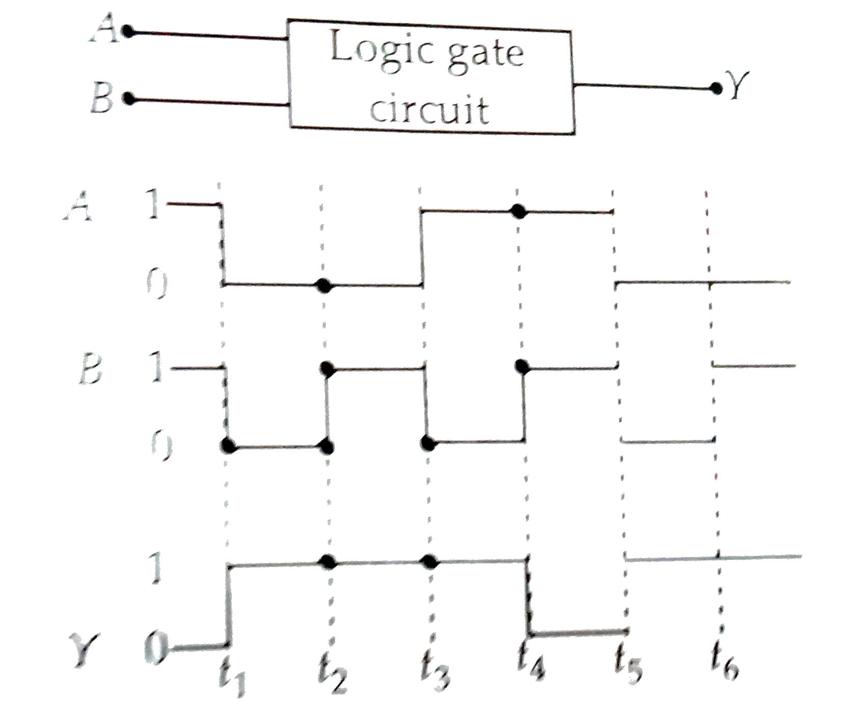
The logic gate isANOR gateBOR gateCAND gateDNAND gate
When the inputs of a two input logic gate are 0 and 0, the output is 1. When the inputs are 1 and 0, the output is zero. The type of logic gate is
View Solution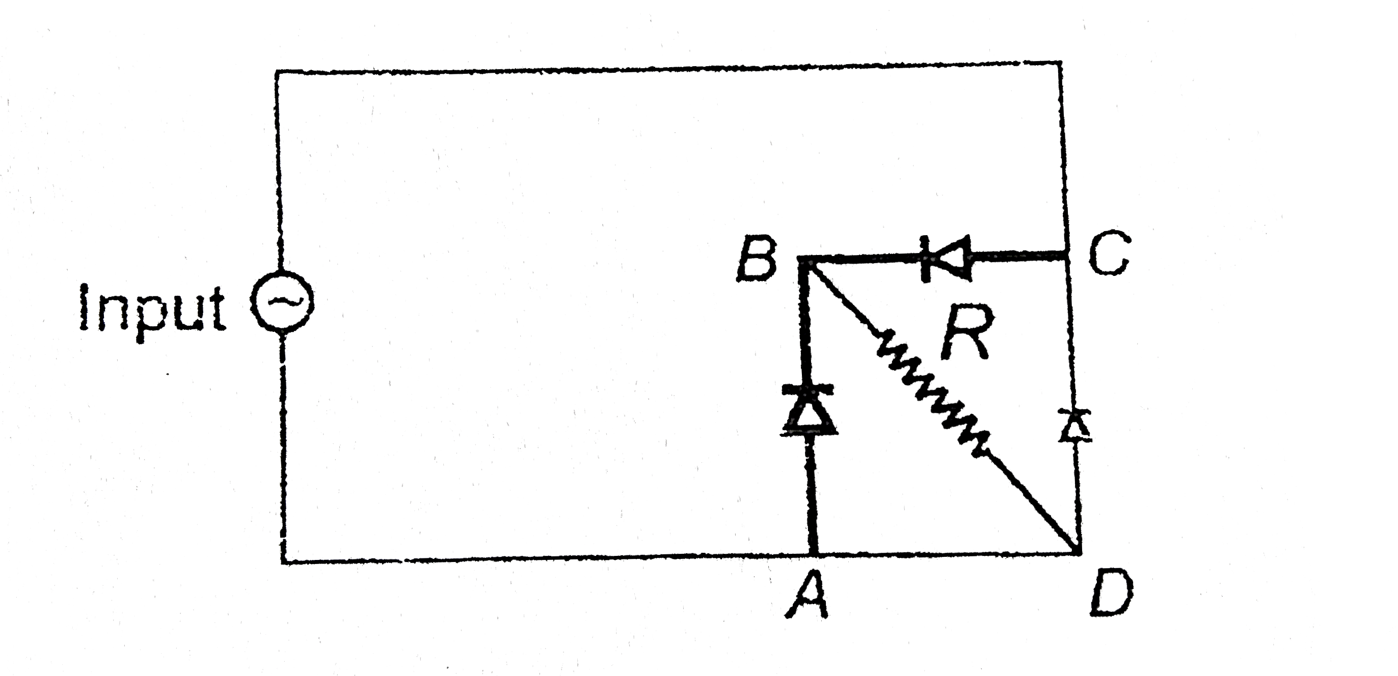
If the input is given between A and C, thent he output at the ends of R will be
View SolutionPotential difference across the terminal of a non ideal battery is
View SolutionThe following figure shows a logic gate circuit with two inputs A and B and the output C. The voltage waveforms of A, B and C are as given The logic circuit is:
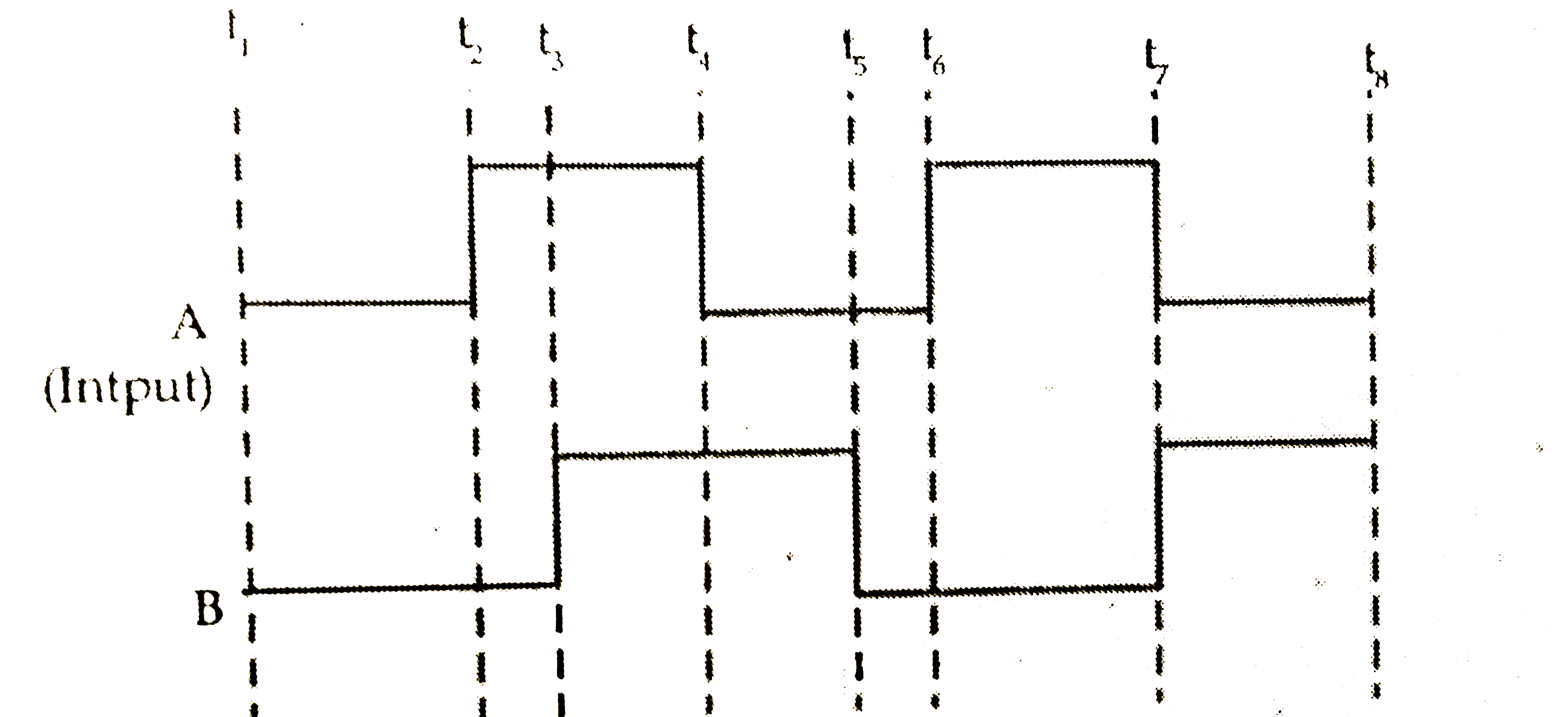
View SolutionThe figure shows the input weveforms A and B for 'AND' gate Draw the output waveform and write the truth table for this logic gate
 .
.
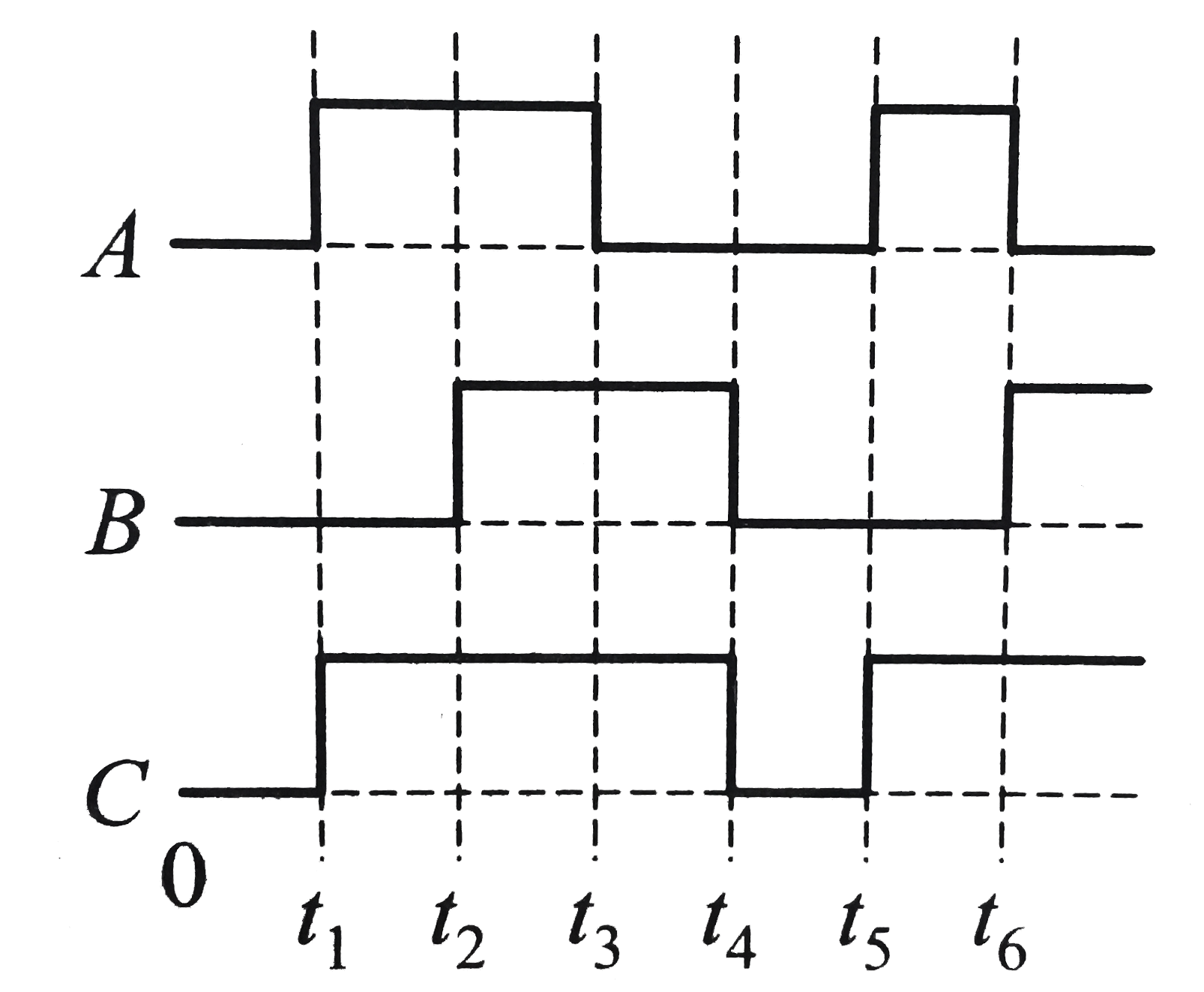
View SolutionThe figure shows a logic circuit with two inputs A and B and the output C. The voltage wave forms across A,B and C are as given. The logic circuit gate is
View SolutionIf A & B are the input as shown in the figure , then output will be

View Solution

