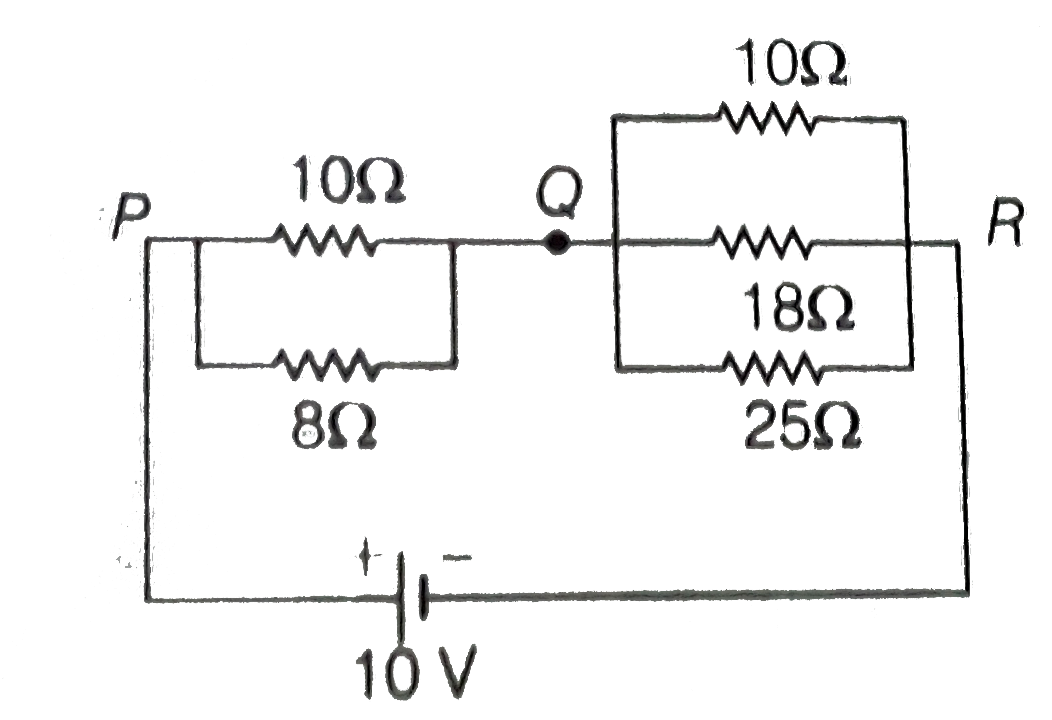
Find in the circuit shown in figure.
A
6.68 V
B
8 V
C
4.35 V
D
7 V
Video Solution
Text Solution
The correct Answer is:C
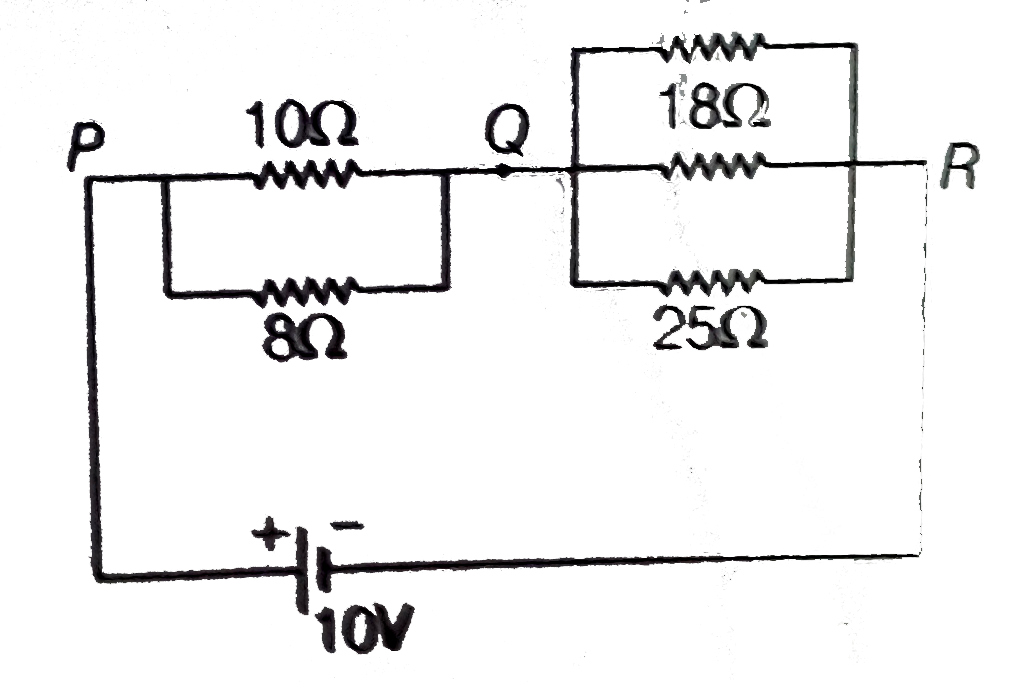
In the given circuit, net resistance between P and Q points is and net resistance between Q and R points is , then
So, circuit will be
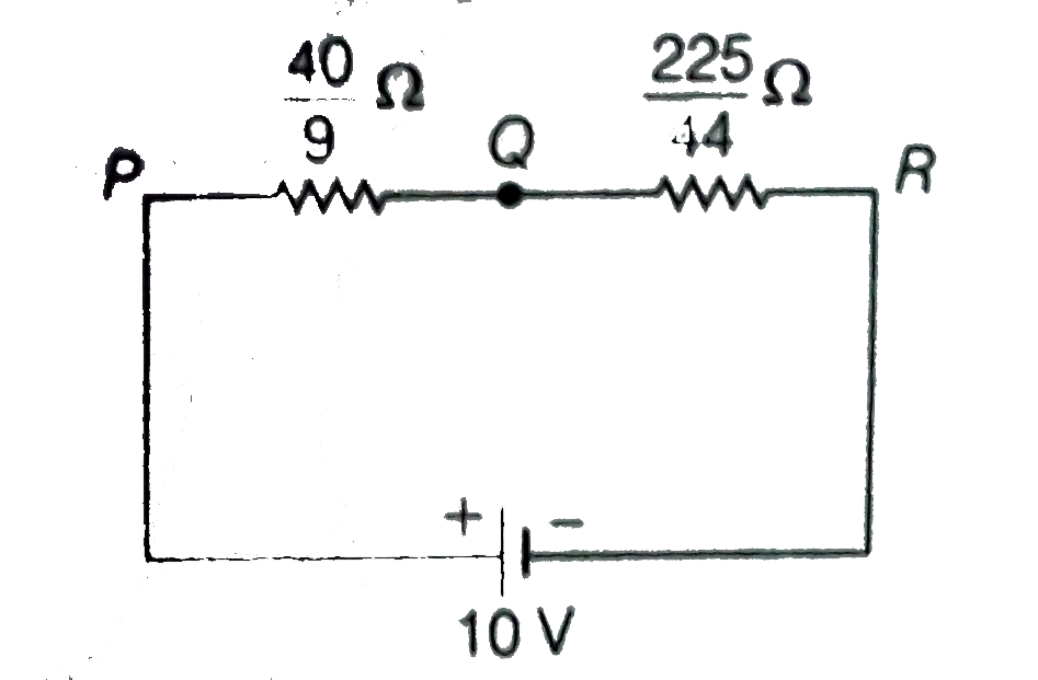
In the series circuit, voltages will be divide in the rartio of their resistances.
or
or V
|
Topper's Solved these Questions
- SOLVED PAPERS 2018BOOK - DC PANDEY ENGLISHCHAPTER - SOLVED PAPERS 2018EXERCISE - Assertion and Reasons
10 Videos
- SOLVED PAPER 2017BOOK - DC PANDEY ENGLISHCHAPTER - SOLVED PAPER 2017EXERCISE - Solved papers 2017(JIPMER)
32 Videos
- WAVE OPTICSBOOK - DC PANDEY ENGLISHCHAPTER - WAVE OPTICSEXERCISE - For JEE Advanced E. Integer Type Questions
13 Videos
Similar Questions
In the circuit shown in figure , V must be
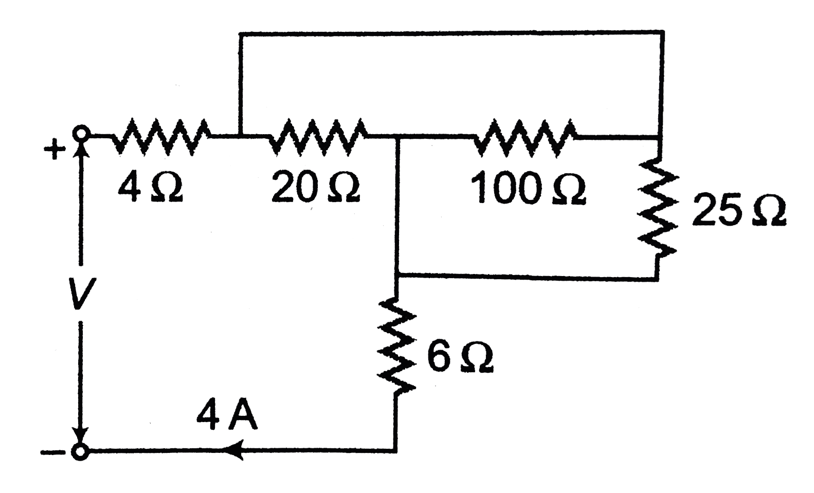
View SolutionIn the circuit shown in figure , V must be

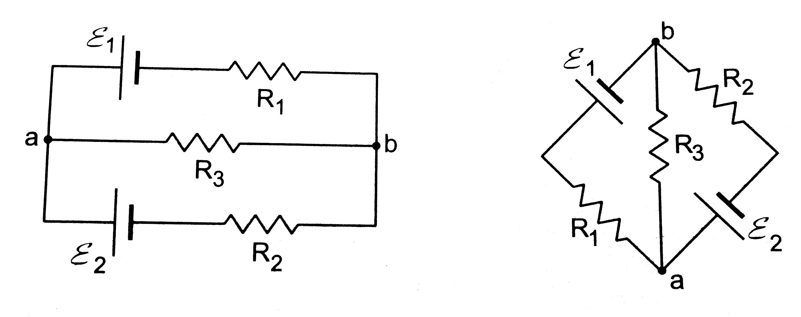
View SolutionFind the potential difference Va−Vbin the circutis shown in figure
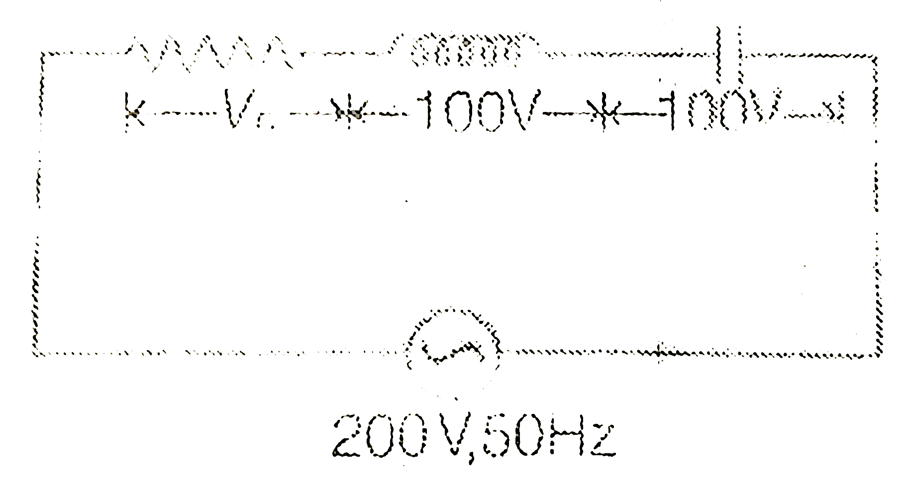
View SolutionIn the circuit shown in figure value of VR is
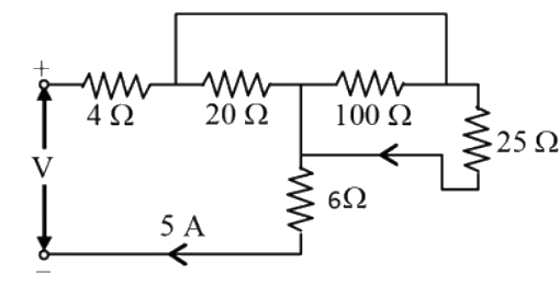
View SolutionIn the circuit shown in the figure , V must be -
View SolutionIn the circuit shown in figure find Vab at 1s

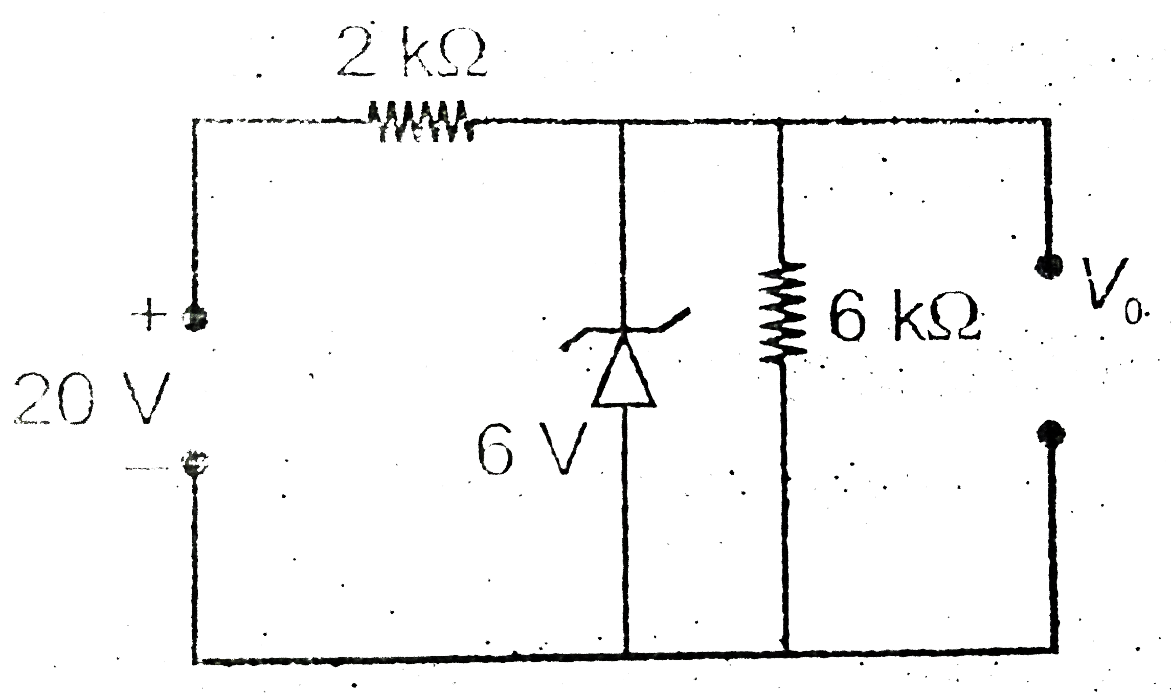
View SolutionWhat is the value of output voltage V0 in the circuit shown in the figure ?
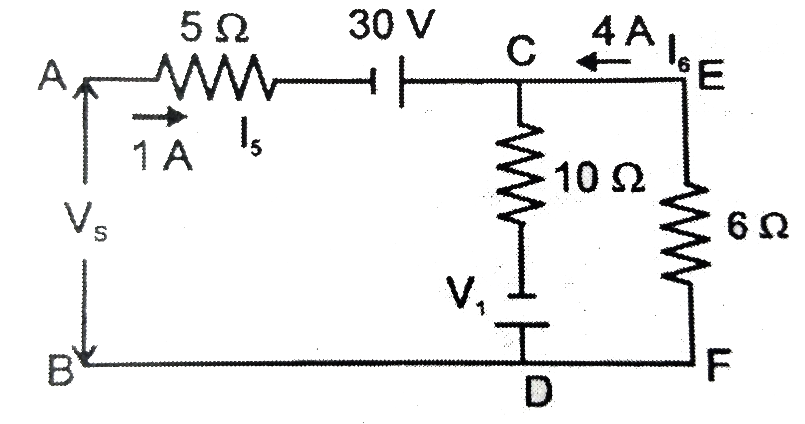
View SolutionFind the current in 10Ω resistcance, V1 and source voltage Vs in the circuit shown in figure (VS=VA−VB)
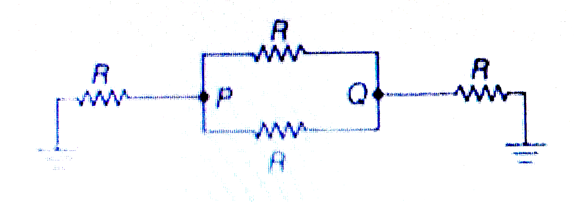
View SolutionThe net resistance between points P and Q in the circuit shown in figure is
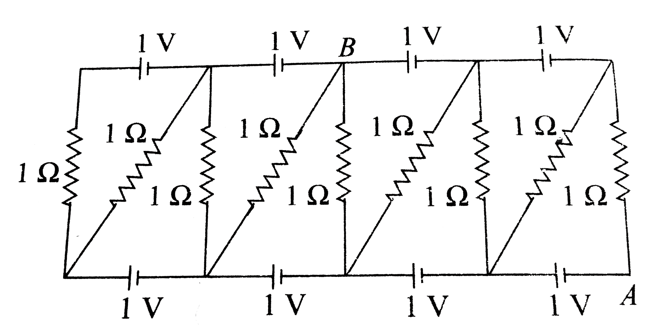
View SolutionThe potential difference VA−VB for the circuit shown in fig. is. −(22/x)V. find the value of x.
View Solution
