Draw the diesel cycle and give the name of the four strokes. Show the work done by the engine on the diagram
To solve the question regarding the diesel cycle, we will follow a step-by-step approach to draw the diesel cycle diagram, label the four strokes, and indicate the work done by the engine.
Step 1: Draw the Axes
- Start by drawing the coordinate axes for the Pressure-Volume (P-V) diagram.
- Label the vertical axis as "Pressure (P)" and the horizontal axis as "Volume (V)".
Hint: Remember that the P-V diagram is crucial for visualizing the processes in the diesel cycle.
Step 2: Plot the Adiabatic Compression (Stroke 1)
- From point 1 to point 2, draw a steep curve that slopes downwards to the right. This represents the adiabatic compression process where the piston compresses the air without any heat exchange.
- Label this stroke as "Adiabatic Compression (1-2)".
Hint: Adiabatic processes are characterized by no heat transfer, so the curve should be steep.
Step 3: Plot the Isobaric Expansion (Stroke 2)
- From point 2 to point 3, draw a horizontal line moving to the right. This represents the isobaric expansion where heat is added at constant pressure.
- Label this stroke as "Isobaric Expansion (2-3)".
Hint: In isobaric processes, pressure remains constant, hence the horizontal line.
Step 4: Plot the Adiabatic Expansion (Stroke 3)
- From point 3 to point 4, draw another steep curve that slopes downwards to the right. This represents the adiabatic expansion where the gas expands doing work on the piston.
- Label this stroke as "Adiabatic Expansion (3-4)".
Hint: Similar to the first stroke, this process also has no heat transfer.
Step 5: Plot the Isochoric Process (Stroke 4)
- From point 4 to point 1, draw a vertical line moving downwards. This represents the isochoric process where the exhaust gases are expelled at constant volume.
- Label this stroke as "Isochoric Process (4-1)".
Hint: Isochoric processes occur at constant volume, leading to a drop in pressure.
Step 6: Indicate Work Done by the Engine
- The work done by the engine during the cycle can be represented by the area enclosed within the cycle on the P-V diagram.
- Shade the area enclosed by the curve formed by the four strokes to indicate the work done.
Hint: The work done is equal to the net area under the curve of the cycle in the P-V diagram.
Final Diagram
- Ensure that all the strokes are clearly labeled and that the area representing the work done is highlighted.
Summary of the Four Strokes:
1. Adiabatic Compression (1-2): Compression of air with no heat exchange.
2. Isobaric Expansion (2-3): Heat addition at constant pressure.
3. Adiabatic Expansion (3-4): Expansion doing work on the piston with no heat exchange.
4. Isochoric Process (4-1): Exhaust of gases at constant volume.
- Start by drawing the coordinate axes for the Pressure-Volume (P-V) diagram.
- Label the vertical axis as "Pressure (P)" and the horizontal axis as "Volume (V)".
- From point 1 to point 2, draw a steep curve that slopes downwards to the right. This represents the adiabatic compression process where the piston compresses the air without any heat exchange.
- Label this stroke as "Adiabatic Compression (1-2)".
- From point 2 to point 3, draw a horizontal line moving to the right. This represents the isobaric expansion where heat is added at constant pressure.
- Label this stroke as "Isobaric Expansion (2-3)".
- From point 3 to point 4, draw another steep curve that slopes downwards to the right. This represents the adiabatic expansion where the gas expands doing work on the piston.
- Label this stroke as "Adiabatic Expansion (3-4)".
- From point 4 to point 1, draw a vertical line moving downwards. This represents the isochoric process where the exhaust gases are expelled at constant volume.
- Label this stroke as "Isochoric Process (4-1)".
- The work done by the engine during the cycle can be represented by the area enclosed within the cycle on the P-V diagram.
- Shade the area enclosed by the curve formed by the four strokes to indicate the work done.
- Ensure that all the strokes are clearly labeled and that the area representing the work done is highlighted.
1. Adiabatic Compression (1-2): Compression of air with no heat exchange.
2. Isobaric Expansion (2-3): Heat addition at constant pressure.
3. Adiabatic Expansion (3-4): Expansion doing work on the piston with no heat exchange.
4. Isochoric Process (4-1): Exhaust of gases at constant volume.
Topper's Solved these Questions
- INTERNAL ENERGY BOOK - ICSECHAPTER - INTERNAL ENERGY EXERCISE - VERY SHORT ANSWER QUESTIONS
17 Videos
- INTERNAL ENERGY BOOK - ICSECHAPTER - INTERNAL ENERGY EXERCISE - SELECTED PROBLEMS (FROM FIRST LAW OF THERMODYNAMICS )
6 Videos
- INTERNAL ENERGY BOOK - ICSECHAPTER - INTERNAL ENERGY EXERCISE - LONG ANSWER QUESTIONS
8 Videos
- GRAVITATIONBOOK - ICSECHAPTER - GRAVITATIONEXERCISE - FROM THE HUBBLE TELESCOP
2 Videos
- MOTION IN FLUIDS BOOK - ICSECHAPTER - MOTION IN FLUIDS EXERCISE - SELECTED PROBLEMS (FROM POISEUILLE.S FORMULA)
19 Videos
Similar Questions
Draw a Carnot cycle and on the diagram mark the work done by the engine.
View SolutionCalculate the work done by the gas in the state diagram shown :
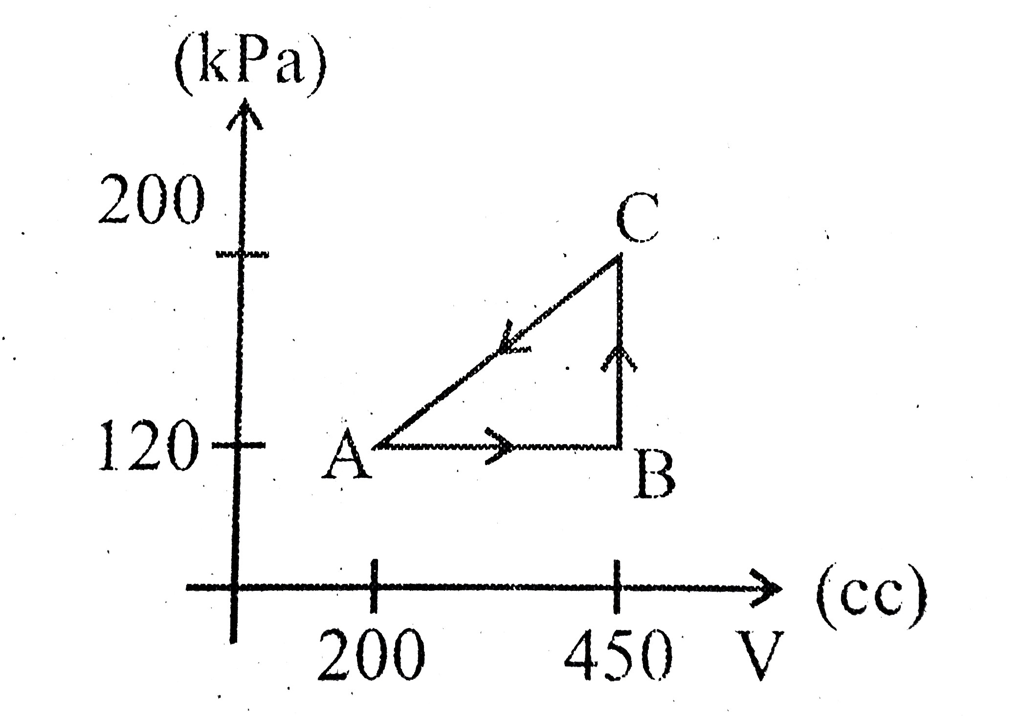
View SolutionA carnot engine takes in 3000 kcal of heat from a reservoir at 627∘C and gives a part of it to a sink at 27∘C. The work done by the engine is
View SolutionThe adjoining diagram shows the velocity versus time plot for a particle . The work done by the force on the particel is positive from
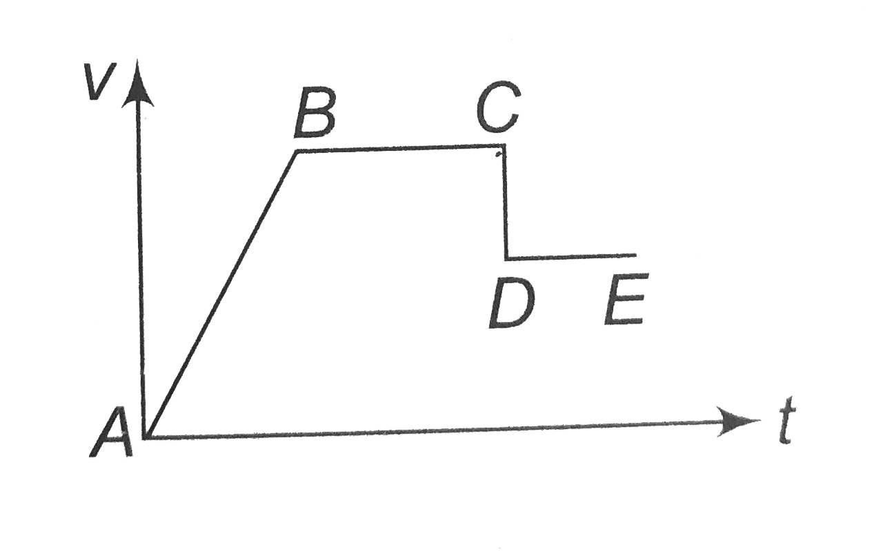
View SolutionA carnot engine works between temperatures 327∘C and 27∘C. If the engine takes 1600 J of heat from the higher temperature reservoir, the work done by the engine per cycle (in Joule) is equal to __________.
View SolutionThe work done by the gas in the process shown in given P-V diagram is
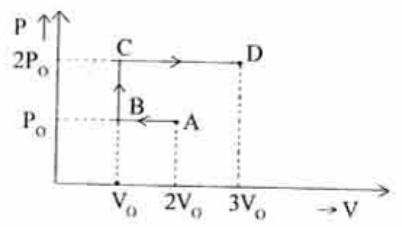
View SolutionAn ideal gas is taken around the cycle ABCA as shown in the P-V diagram. The total work done by the gas during the cycle is
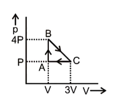
View SolutionAn ideal gas is taken around the cycle ABCD shown in the PV diagram below. The net work done by the gas during the cycle is equal to
View SolutionA Carnot engine takes 3×10⁶ cal of heat from a reservoir at 627∘C and gives it to a sink at 27∘C. The work done by the engine is:
View SolutionA Carnot engine takes 3×10⁶ cal of heat from a reservoir at 627∘C and gives it to a sink at 27∘C. The work done by the engine is:
View Solution
