Draw the circuit symbol of photodiode.
To draw the circuit symbol of a photodiode, follow these steps:
Step 1: Draw the Basic Diode Symbol
- Start by drawing the basic symbol of a diode, which consists of a triangle pointing towards a line. The triangle represents the anode, and the line represents the cathode.
Step 2: Label the Terminals
- Label the left side of the triangle as the anode (A) and the line on the right side as the cathode (K). This indicates the direction of conventional current flow.
Step 3: Add the Light Arrows
- To indicate that this is a photodiode, draw arrows pointing towards the diode symbol. These arrows represent light (photons) striking the photodiode.
Step 4: Finalize the Drawing
- Ensure that the arrows are clearly visible and that the diode symbol is neat. You can also label the symbol as "Photodiode" for clarity.
Final Representation
- The final drawing should show a diode symbol with arrows indicating incoming light, clearly labeled as a photodiode.
---
- Start by drawing the basic symbol of a diode, which consists of a triangle pointing towards a line. The triangle represents the anode, and the line represents the cathode.
- Label the left side of the triangle as the anode (A) and the line on the right side as the cathode (K). This indicates the direction of conventional current flow.
- To indicate that this is a photodiode, draw arrows pointing towards the diode symbol. These arrows represent light (photons) striking the photodiode.
- Ensure that the arrows are clearly visible and that the diode symbol is neat. You can also label the symbol as "Photodiode" for clarity.
- The final drawing should show a diode symbol with arrows indicating incoming light, clearly labeled as a photodiode.
Similar Questions
Ar is symbol of
View SolutionName an instrument that measures potential difference between two points in a circuit.
Difine the unit of potential difference in terms of SI unit of charge and work . Draw the
circuit symbols for a (i) veribale resisitor , (ii) a plug key which is closed one .
Two electric circutirs I and II are shown below.
(i) Which of the two circuits has more resistance?
(ii) Through which circuit more current passes?
(iii) In which circuit, the potential difference across each resistor is equal?
(iv) If R1>R2>R3, in which circuit more heat will be produced in R1 as compared to
other two resistors?
 .
.
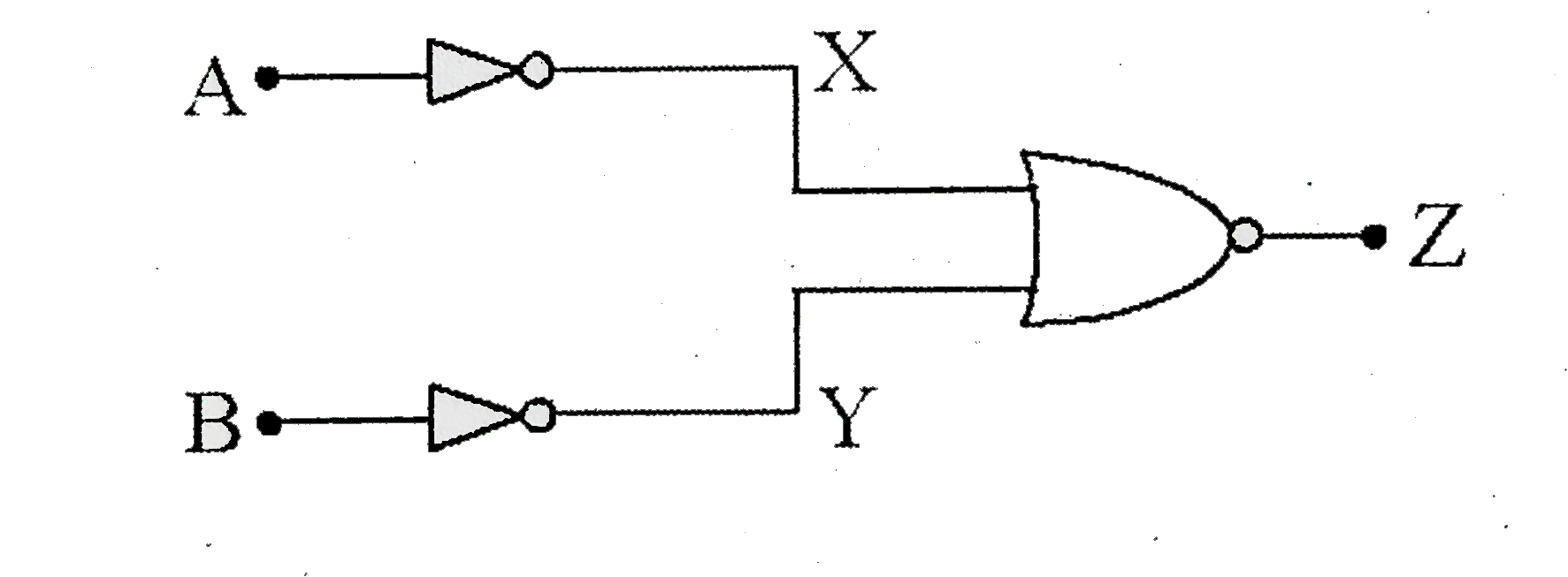
View SolutionYou are given a circuit below. Write its truth table. Hence, identify the logic operation carried out by this circuit. Draw the logic symbol of the gate it corresponds to.

View Solution
You are given a circuit below. Write its truth table. Hence, identify the logic operation carried out by this circuit. Draw the logic symbol of the gate it corresponds to.
View SolutionDraw the Lewis symbols of the following elements.
Na, Ca, Br, Xe, As, Ge
View SolutionDraw the lewis symbol for Nitrogen and Sulphur.
View SolutionDraw the Lewis symbol for the following nitrogen (N) and fluorine (F)
View Solution

(a) Draw the circuit diagram of reversed bias p-n junction.
(b). Draw the output wavefrom across diode in given circuit.
(c). Draw the truth table for the given logic gate.
View SolutionDraw the circuit diagram of a half - wave rectifier using a p-n junction diode.
View SolutionExplain the formation of depletion layer and potential barrier in p-n junction.
Draw the circuit diagram of a half wave rectifier and explain its working.
View Solution
