In the circuit shown in figure initially the switch is opened. The switch is closed now.
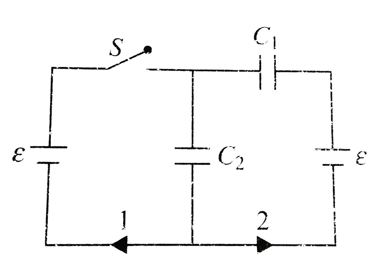
The charge that will flow in direction 1 is
−C22εC1+C2
−(C1C2C1+C2)ε
C21εC1+C2
C2ε
The correct Answer is:B
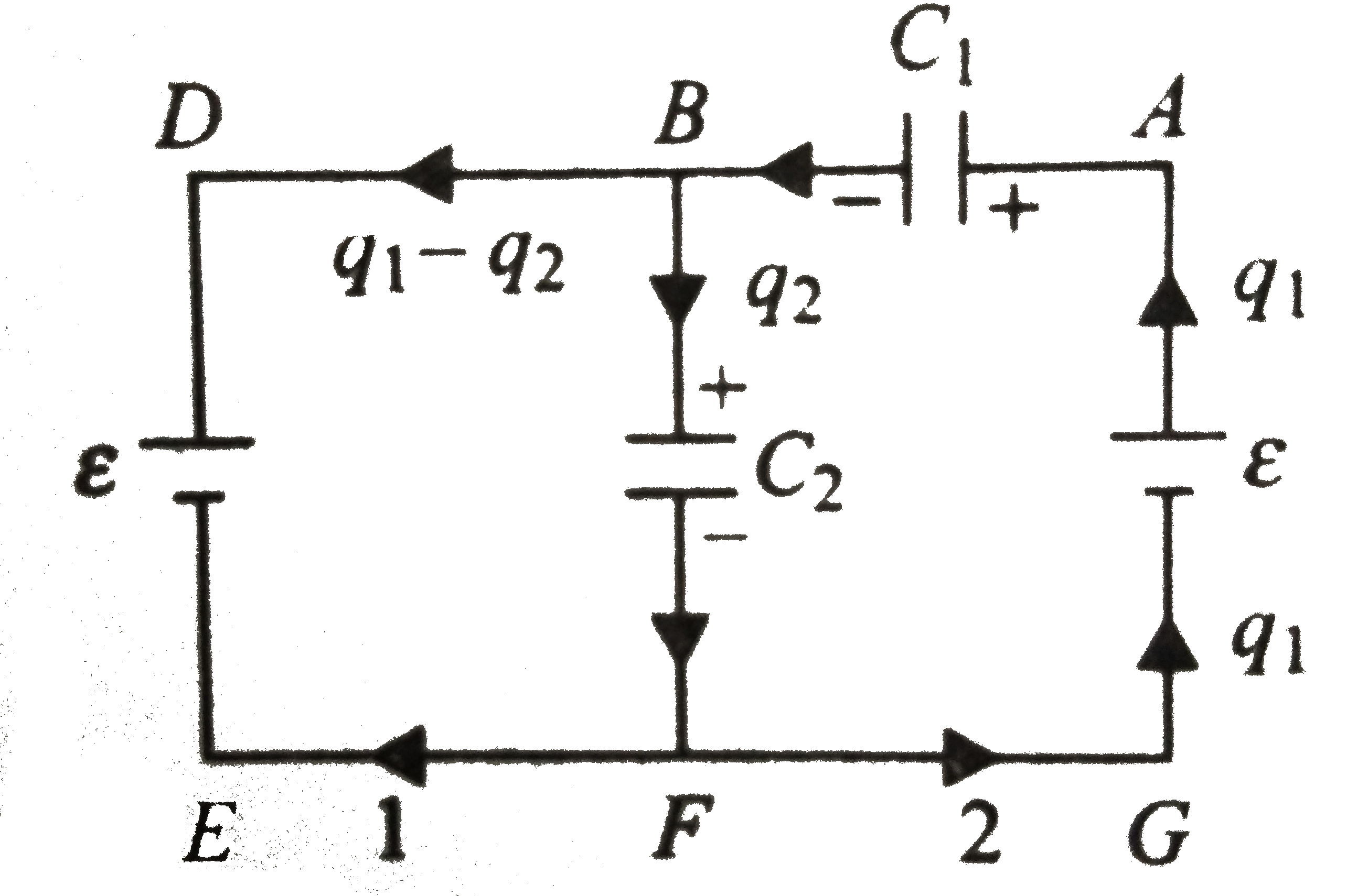
Charge on capacitors C1 and C2 before closing the switch S is
q0=(C1C2C1+C2)ε
After closing S, charge in C2 (final charge) is
q2=C2ε
In loop ABBDEFGA,ε=0 or q1=0 ltbr> final charge on C1,q1=0 to make final charge in C1 the charge hence charge flown towards direction 2 is
△q2=−(C1C2C1+C2)ε
To make charge on capacitor C2 to final value q2 the charge flow into capacitor is
△q=C2ε−C1C2C1+C2εg=C2ε[1−C1C1+C2]
△qB=C22εC1+C2 ltbr> at junction F,
△q1=△q−△q2=C2εC1+C2[C2+C1]=C2ε
Alternative method: fig
in loop ABDEG,−(q0+△q1)C1−ε+ε=0
or tr∈g≤1=−q0=−C1C2εC1+C2
in loop BFEDB, −(q0+△q1)C2+ε=0
or △q=C2ε−q0
At junction F
△q2=△q1−△q=−q0−(C2ε−q0)=−C2ε
Hence charge flow in the direction of
(1)is−C1C2εC1+C2
(2). is C2ε
Topper's Solved these Questions
- MISCELLANEOUS VOLUME 3BOOK - CENGAGE PHYSICS ENGLISHCHAPTER - MISCELLANEOUS VOLUME 3EXERCISE - Interger Answer type
20 Videos
- MISCELLANEOUS VOLUME 3BOOK - CENGAGE PHYSICS ENGLISHCHAPTER - MISCELLANEOUS VOLUME 3EXERCISE - Fill in the blanks
10 Videos
- MISCELLANEOUS VOLUME 3BOOK - CENGAGE PHYSICS ENGLISHCHAPTER - MISCELLANEOUS VOLUME 3EXERCISE - Assertion and Reason Type
8 Videos
- MAGNETIC FIELD AND MAGNETIC FORCESBOOK - CENGAGE PHYSICS ENGLISHCHAPTER - MAGNETIC FIELD AND MAGNETIC FORCESEXERCISE - Multiple Correct Answer type
2 Videos
- MISCELLANEOUS VOLUME 5BOOK - CENGAGE PHYSICS ENGLISHCHAPTER - MISCELLANEOUS VOLUME 5EXERCISE - Integer
12 Videos
Similar Questions
In the circuit shown in figure initially the switch is opened. The switch is closed now.
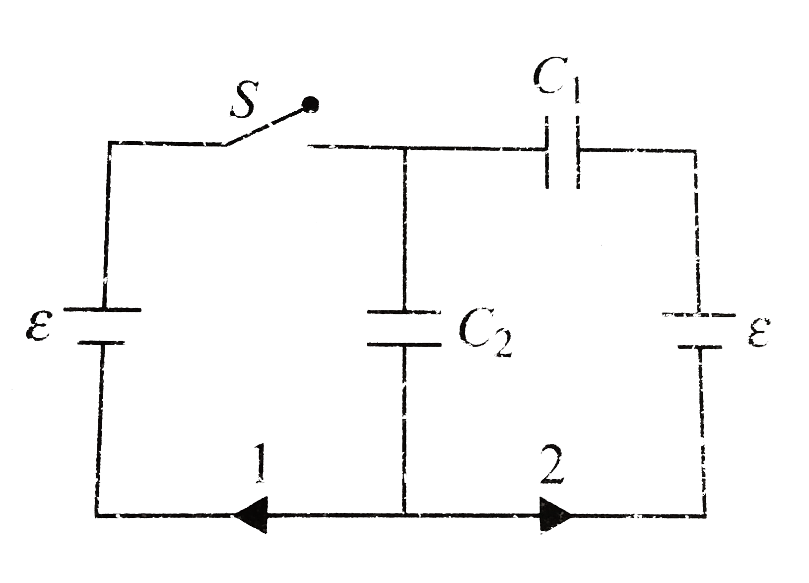
The charge that will flow in direction 2 is
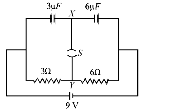
View SolutionA circuit is connected as shown in the figure with the switch S open. When the switch is closed, the total amount of charge that flows from Y to X is
 .
.
View SolutionIf the switch is closed then current will flow.
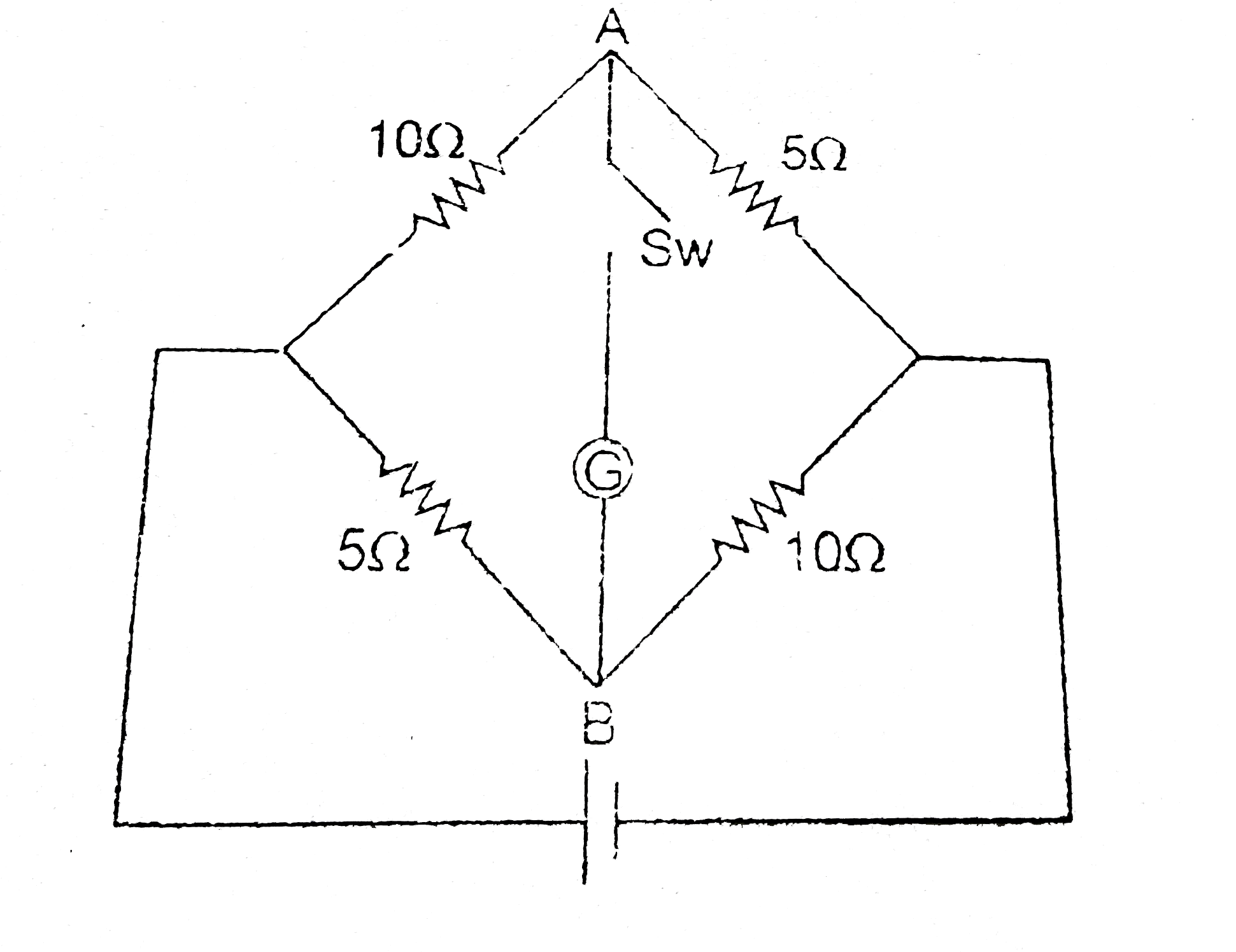
View SolutionIn the circuit diagram shown in figure, initially switch S is opened and the circuit is in steady state. At time t=0, the switch S is closed and the new steady state is reached after some time. Choose the correct option(s)
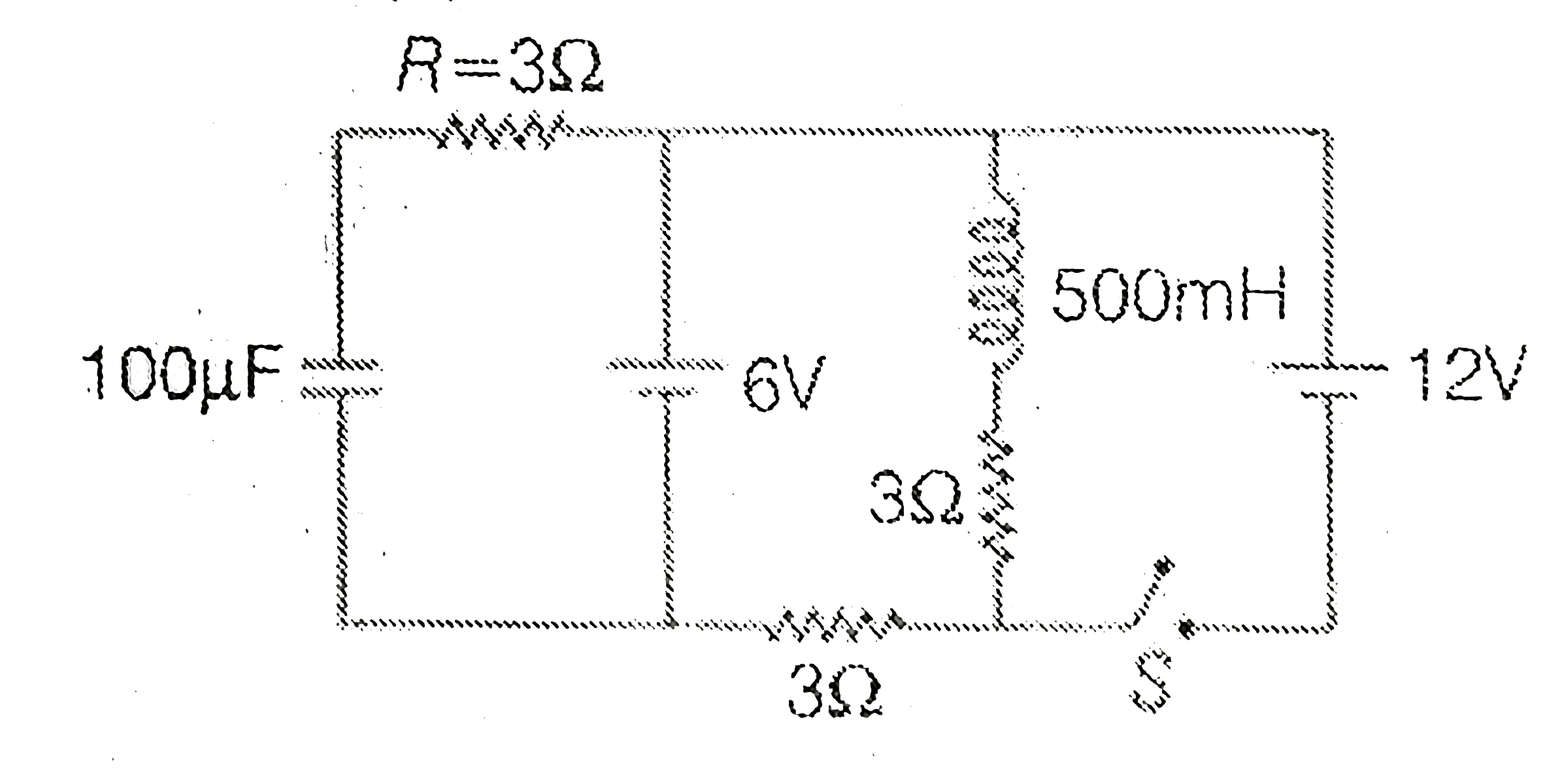
View SolutionIn the circuit shown in figure the switch S is closed at t = 0. A long time after closing the switch
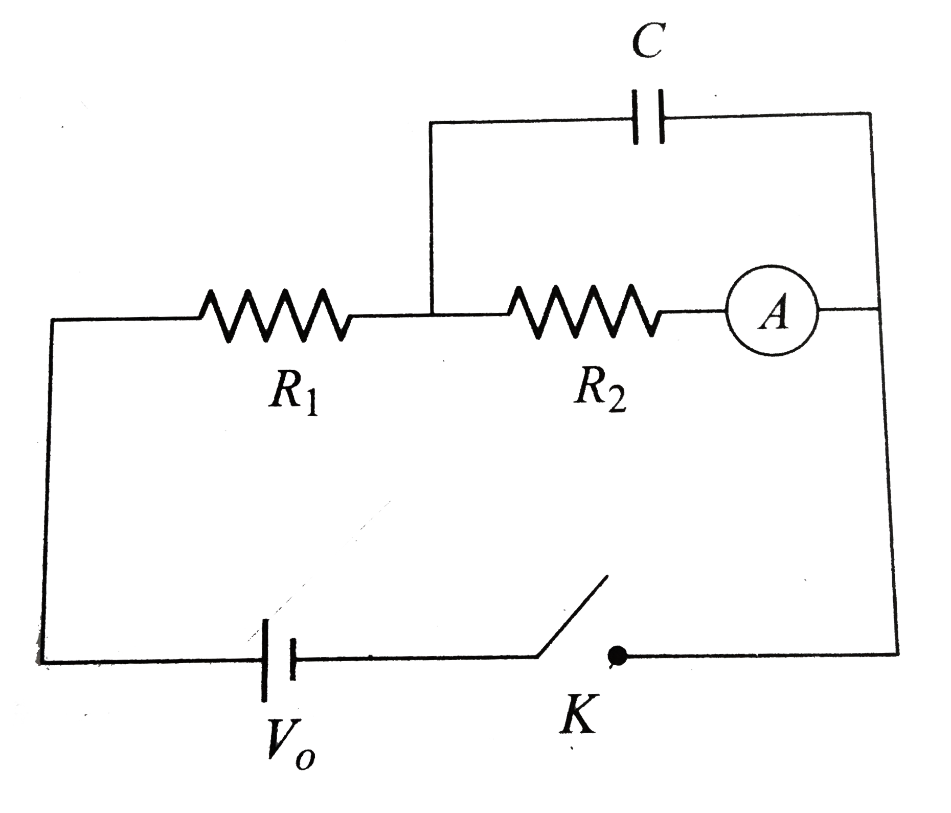
View SolutionIn the connection shown in the figure, initially the switch K is open and the capacitor is uncharged. Then the switch is closed, and the capacitor is charged up to the steady state and the switch is opened again. Determine the values indicated by the values indicated by the ammeter just after closing the switch
[GivenV0=30V,R1=10kΩ,R2=5kΩ]
 .
.
A long time after switch was closed.
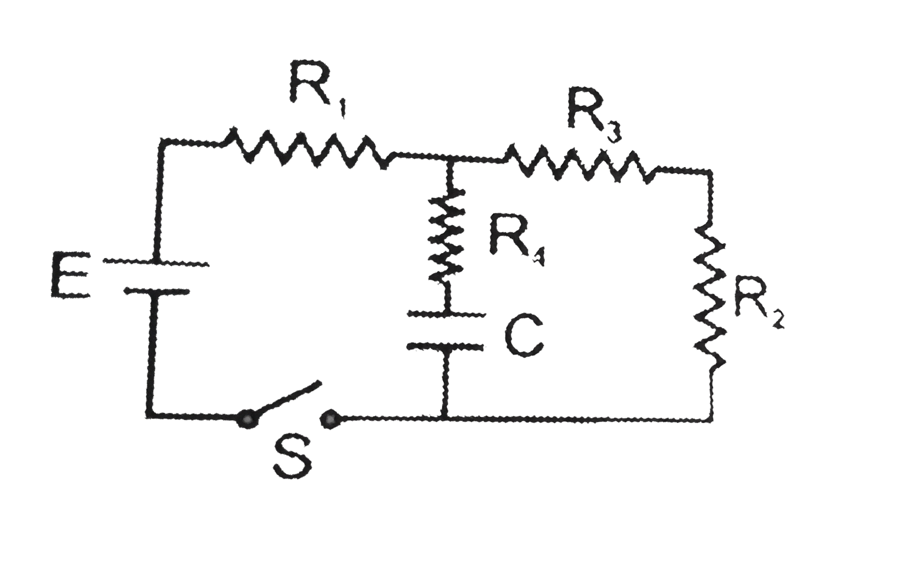
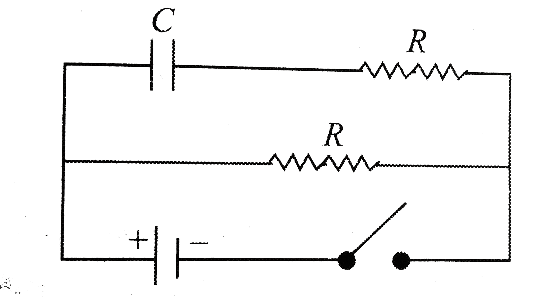
View SolutionIn the circuit shown in fig. when the switch is closed, the capacitor charges with a time constant
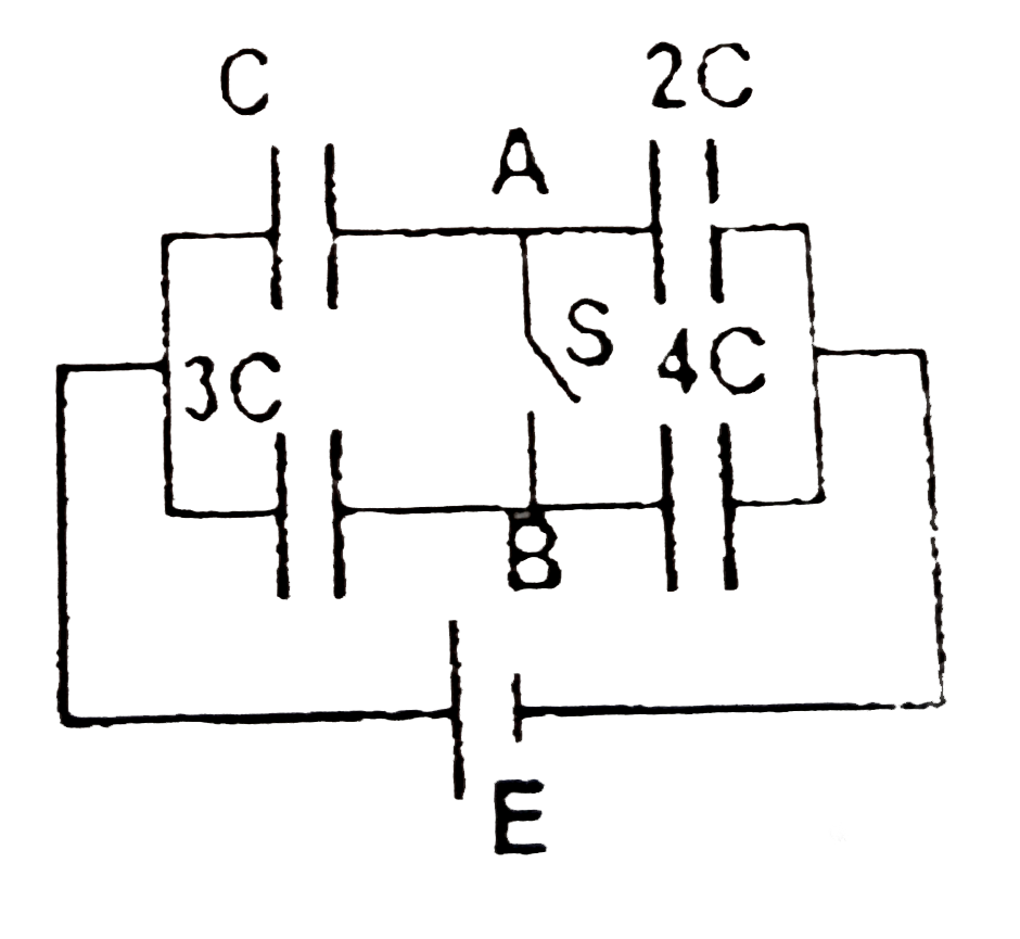
View SolutionFour capacitors of capacitance C, 2C, 3C & 4C respectively are connected as shown in figure. Battery is ideal and all the connected wires have no resistance capcitance or inductance. Initially the switch S is open. If at t=0 switch S is closed
The charge flown through connector AB after switch is closed is
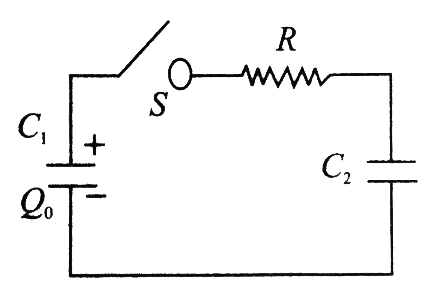
View SolutionIn the circuit shown, the capacitor C1 is initially charged with charge q0. The switch S is closed at time t = 0 . The charge on C2 after time t is
View SolutionConsider the circuit shown in figure, after switch S is closed.
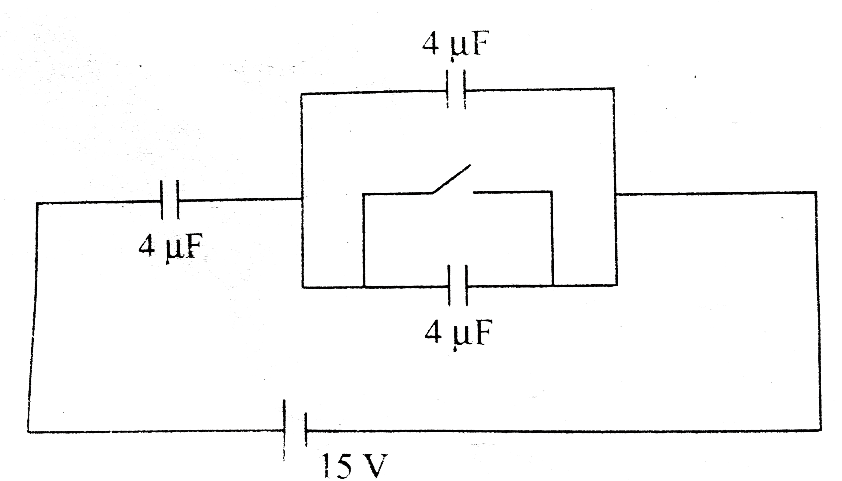
What amount of charge will flow through the switch?
View Solution
