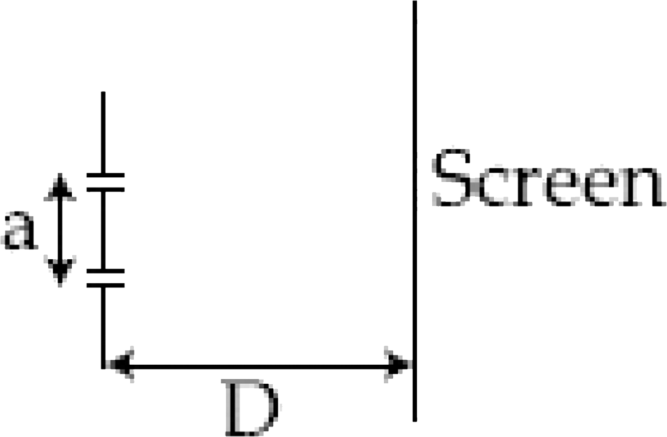
A transparent slab of thickness t and refractive index μ is inserted in front of upper of YDSE apparauts. The wavelength of ligth used. is λ. Assume that there is no absorption of light by the slab. Mark the correct statement(s).
The intensity of dark fringes will be 0, if slits are identical
The change in optical path due to insertion of plate is μt.
The change in optical path due to insertion of plate is(μ−1)t
For making intensity zero at center of screen, the thickness can be 5λ2(μ−1).
The correct Answer is:a.,c.,d
To solve the problem, we need to analyze the effect of inserting a transparent slab of thickness t and refractive index μ in front of one of the slits in a Young's Double Slit Experiment (YDSE). We will determine the changes in optical path and the implications for interference patterns.
1. Understanding Optical Path:
- The optical path length is defined as the product of the physical path length and the refractive index of the medium through which the light travels.
- In air, the optical path length is simply the distance traveled, but in a medium with refractive index μ, it is given by Optical Path=Physical Path×μ.
2. Path Difference Without Slab:
- In the absence of the slab, the path difference Δx between the two waves arriving at point P on the screen is given by:
Δx=S2P−S1P
- If P is at a distance y from the center, this can be expressed as:
Δx=yDd
where D is the distance from the slits to the screen, and d is the distance between the slits.
3. Path Difference With Slab:
- When the slab is inserted in front of slit S1, the light traveling through S1 will now have to pass through the slab.
- The effective path length for the wave traveling through S1 becomes:
S1P′=S1P−t
- The optical path length for the wave traveling through the slab is:
Optical Path for S1=(S1P−t)+μt=S1P+(μ−1)t
- Therefore, the new path difference becomes:
Δx′=S2P−(S1P+(μ−1)t)=Δx−(μ−1)t
4. Condition for Dark Fringes:
- For destructive interference (dark fringes), the path difference must be an odd multiple of half the wavelength:
Δx′=(2n+1)λ2,n=0,1,2,…
- Substituting for Δx′:
Δx−(μ−1)t=(2n+1)λ2
5. Finding Thickness t:
- Rearranging the equation gives:
t=Δx−(2n+1)λ2μ−1
- This shows how the thickness t relates to the path difference and the refractive index.
6. Conclusion:
- The correct statements regarding the effect of the slab on the interference pattern can be derived from the above analysis. Specifically, we can conclude:
- The path difference changes due to the presence of the slab.
- The conditions for dark fringes will depend on the thickness of the slab and the refractive index.
- The optical path length is defined as the product of the physical path length and the refractive index of the medium through which the light travels.
- In air, the optical path length is simply the distance traveled, but in a medium with refractive index μ, it is given by Optical Path=Physical Path×μ.
- In the absence of the slab, the path difference Δx between the two waves arriving at point P on the screen is given by:
Δx=S2P−S1P
- If P is at a distance y from the center, this can be expressed as:
Δx=yDd
where D is the distance from the slits to the screen, and d is the distance between the slits.
- When the slab is inserted in front of slit S1, the light traveling through S1 will now have to pass through the slab.
- The effective path length for the wave traveling through S1 becomes:
S1P′=S1P−t
- The optical path length for the wave traveling through the slab is:
Optical Path for S1=(S1P−t)+μt=S1P+(μ−1)t
- Therefore, the new path difference becomes:
Δx′=S2P−(S1P+(μ−1)t)=Δx−(μ−1)t
- For destructive interference (dark fringes), the path difference must be an odd multiple of half the wavelength:
Δx′=(2n+1)λ2,n=0,1,2,…
- Substituting for Δx′:
Δx−(μ−1)t=(2n+1)λ2
- Rearranging the equation gives:
t=Δx−(2n+1)λ2μ−1
- This shows how the thickness t relates to the path difference and the refractive index.
- The correct statements regarding the effect of the slab on the interference pattern can be derived from the above analysis. Specifically, we can conclude:
- The path difference changes due to the presence of the slab.
- The conditions for dark fringes will depend on the thickness of the slab and the refractive index.
Topper's Solved these Questions
- BOOK - CENGAGE PHYSICS ENGLISHCHAPTER - WAVE OPTICSEXERCISE - Multiple Correct8videos
WAVE OPTICS
- BOOK - CENGAGE PHYSICS ENGLISHCHAPTER - WAVE OPTICSEXERCISE - Assertion- Reasoning13videos
WAVE OPTICS
- BOOK - CENGAGE PHYSICS ENGLISHCHAPTER - WAVE OPTICSEXERCISE - Subjective11videos
WAVE OPTICS
- BOOK - CENGAGE PHYSICS ENGLISHCHAPTER - SOURCES OF MAGNETIC FIELDEXERCISE - single correct Ansewer type12videos
SOURCES OF MAGNETIC FIELD
Similar Questions
When a transparent parallel plate of uniform thickness t and refractive index μ is interposed normally in the path of a beam of light, the optical path is
View SolutionA transparent glass plate of thickness 0.5 mm and refractive index 1.5 is placed infront of one of the slits in a double slit experiment. If the wavelength of light used is 6000A∘, the ratio of maximum to minimum intensity in the interference pattern is 25/4. Then the ratio of light intensity transmitted to incident on thin transparent glass plate is
View SolutionIn YDSE when slab of thickness t and refractive index μ is placed in front of one slit then central maxima shifts by one fringe width. Find out t in terms of λ and μ.
View SolutionThe figure shows a Young's double slit experimental setup. It is observed that when a thin transparent sheet of thickness t and refractive index μ is put front of one of the slits, the central maximum gets shifted by a distance equal to n fringe widths. If the wavelength of light used is λ, t will be :
 View Solution
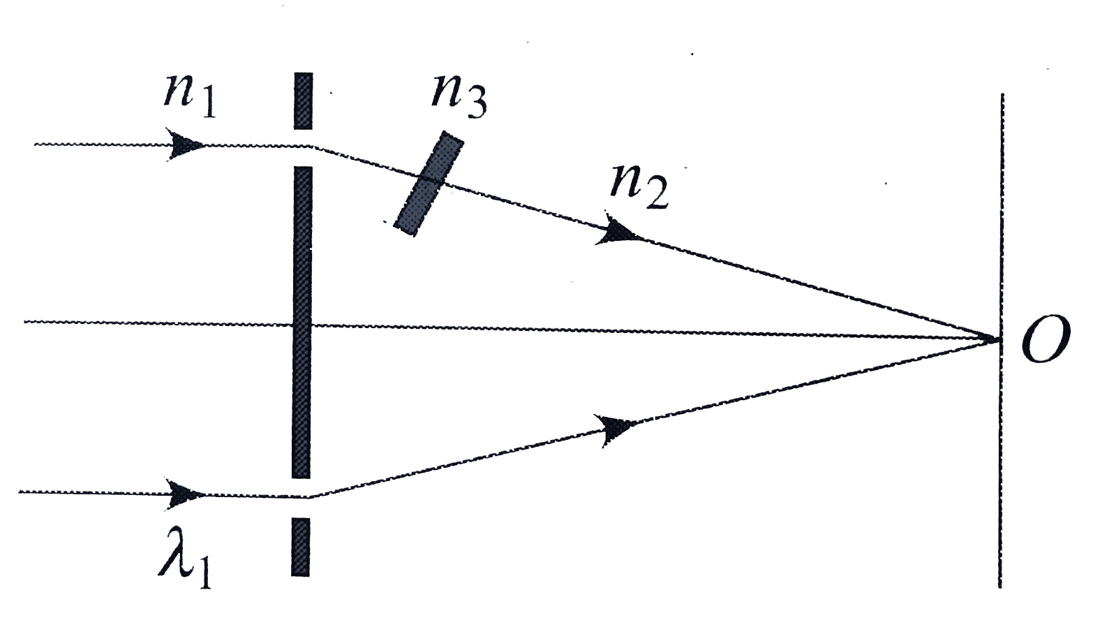
In YDSE shown in figure a parallel beam of light is incident on the slits from a medium of refractive index n1. The wavelength of light in this medium is λ1. A transparent slab of thickness t and refractive index n3 is put in front of one slit. The medium between the screen and the plane of the slits is n2. The phase difference between the light waves reaching point O (symmetrical, relative to the slits) is
 View Solution
A thin mica sheet of thickness 4×10⁻⁶ m and refractive index (μ=1.5) is introduced in the path of the light from upper slit. The wavelength of the wave used is 5000Å The central bright maximum will shift
View SolutionIn YDSE, slab of thickness t and refractive index μ is placed in front of any slit. Then displacement of central maximu is terms of fringe width when light of wavelength λ is incident on system is
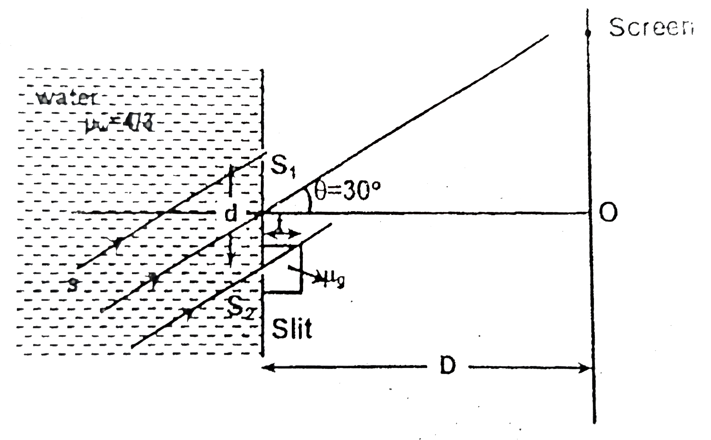
View SolutionIn a YDSE experiment the two slits are covered with a transparent membrane of negligible thickness which allows light to pass through it but does not allow water. A glass slab of thickness t=0.41mm and refractive index μg=1.5 is placed infront of one of the slits as shown in the figure. The separation between the slits is d=0.30mm. The entire space to the left of the slits is filled with water of refractive index μw=4/3.
A coherent light of intensity I and absolute wavelength λ=5000Å is being incident on the slits making an angle 30∘ with horizontal. If screen is placed at a distance D=1m from the slits, find
(a) the position of central maxima.
(b) the intensity at point O.
 View Solution
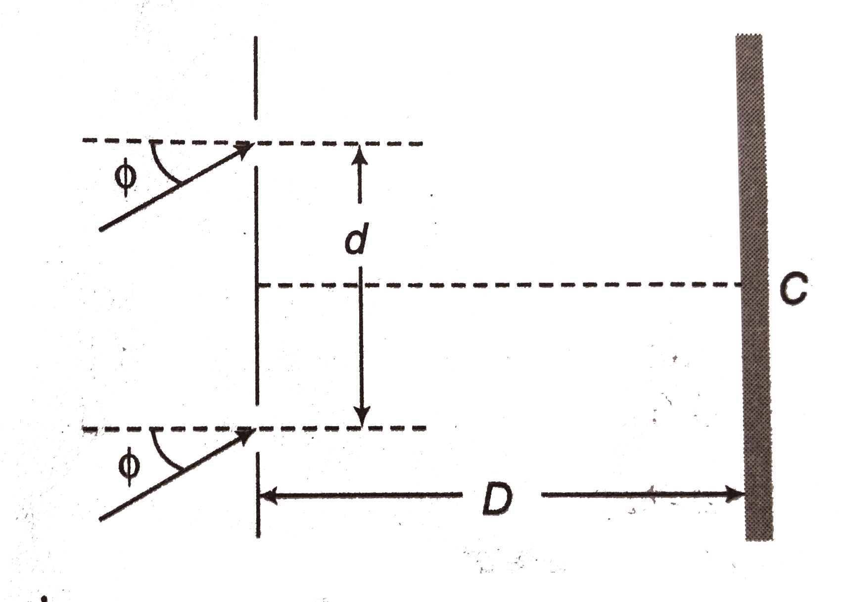
Light of wavelengthλ=500nm falls on two narrow slits placed a distance d = 50×10−4 cm
apart, at an angle ϕ=30∘ relative to the slits as shown in figure. On the lower slit a transparent slab of thickness 0.1 mm and refractive index 32 is placed. The interference pattern is observed at a distance D=2m from the slits. Then, calculate

(a) position of the central maxima.
(b) the order of maxima at point C of screen .
(c)how many fringes will pass C, if we remove the transparent slab from the lower slit?View SolutionIn a doulble slit experiment when a thin film of thickness t having refractive index μ is introduced in from of one of the slits, the maximum at the centre of the fringe pattern shifts by one width. The value of t is (λ is the wavelength of the light used)
View Solution

