Figure shows an LCR circuit. When the switch is closed, the currents through resistor R, inductor L, and capacitor C are I1,I2, and I3, respectively. Determine the values of I1,I2, and I3.
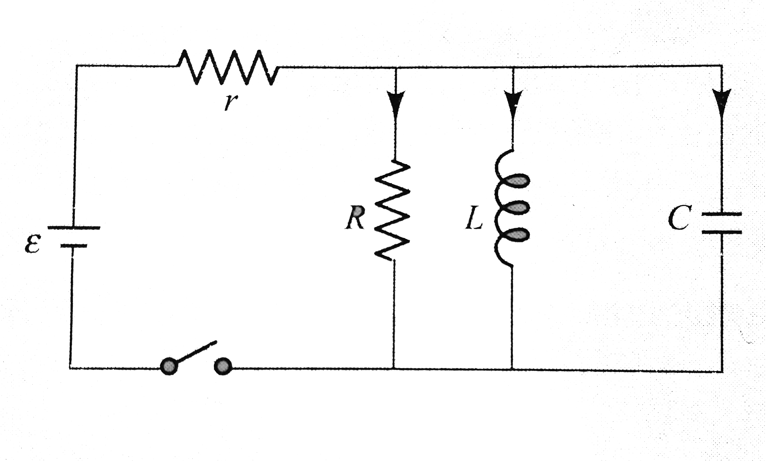
a. at t=0 b. at t=∞
At t=0, C will act as a simple wire, so R and L both will be short-circuited. So that there is no current in R and L.
I1=0,I2=0,I3=εr
At t=∞, will act as as a simple wire so, R and C will be short-circuited.
I1=0,I2=εr,I3=0
Topper's Solved these Questions
- BOOK - CENGAGE PHYSICS ENGLISHCHAPTER - INDUCTANCEEXERCISE - Exercises (subjective)7videos
INDUCTANCE
- BOOK - CENGAGE PHYSICS ENGLISHCHAPTER - INDUCTANCEEXERCISE - Exercises (single Correct )65videos
INDUCTANCE
- BOOK - CENGAGE PHYSICS ENGLISHCHAPTER - INDUCTANCEEXERCISE - Solved Examples3videos
INDUCTANCE
- BOOK - CENGAGE PHYSICS ENGLISHCHAPTER - HEATING EFFECT OF CURRENTEXERCISE - Thermal Power in Resistance Connected in Circuit27videos
HEATING EFFECT OF CURRENT
- BOOK - CENGAGE PHYSICS ENGLISHCHAPTER - MAGNETIC FIELD AND MAGNETIC FORCESEXERCISE - Multiple Correct Answer type2videos
MAGNETIC FIELD AND MAGNETIC FORCES
Similar Questions
Figure shows an L-R circuit. When the switch S is closed, the current through resistor R1,R2 and l3 are l1,l2 and l3 respectively. The value of l1,l2 and l3 at t=0 s is
View SolutionFor the circuit shown in figure below, at t = 0, switch is closed, the initial current through resistor and final charge on capacitor are
 View Solution
Knowledge Check
- Question 1 - Select One
In the circuit shown, the value of currents I1,I2andI3 are
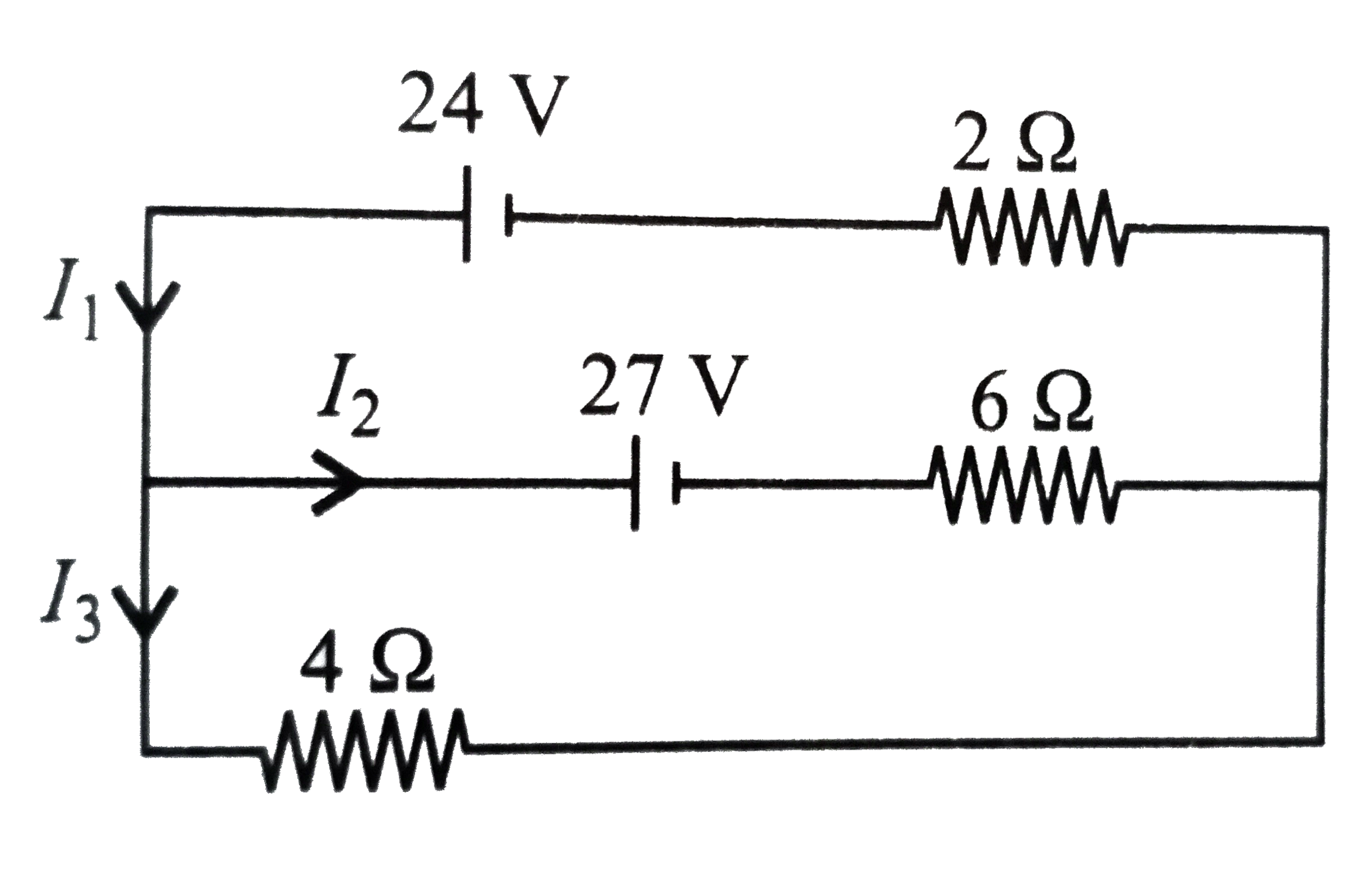 A3A,−3A2A,92AB92A,−32AC5A,4A,−3AD7A,54A,92A
In the circuit shown, the switch is closed at t=0, the currents I1,I2 and I3 are
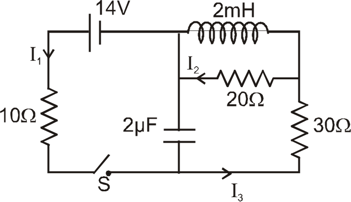 View Solution
Find the current I1, I2, & I3, in the circuit.
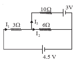 View Solution
Switch is closed at t=0 then the current in the circuit at t=L2R is
_PHY_E06_157_Q01.png) View Solution
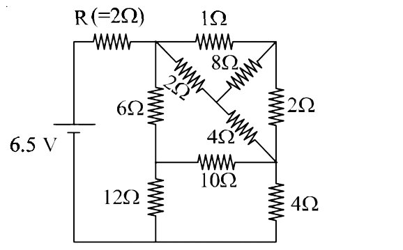
View SolutionIn the following circuit, the current through the resistor R(=2Ω) is I amperes. The value of I is
 View Solution
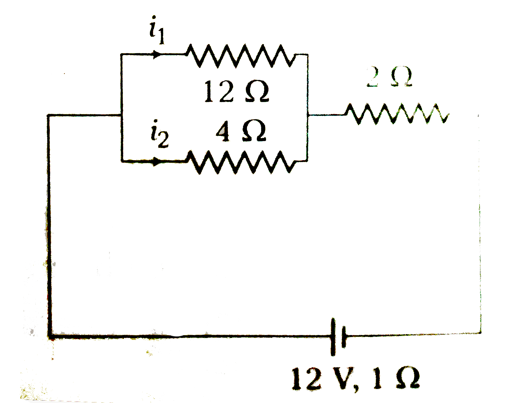
In the circuit shown, the currents i1 and i2 are
 View Solution
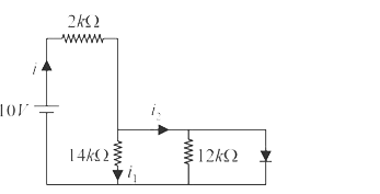
In the following circuit i1 and i2 are respectively
 View Solution
In the circuit shown in figure switch S is closed at time t=0
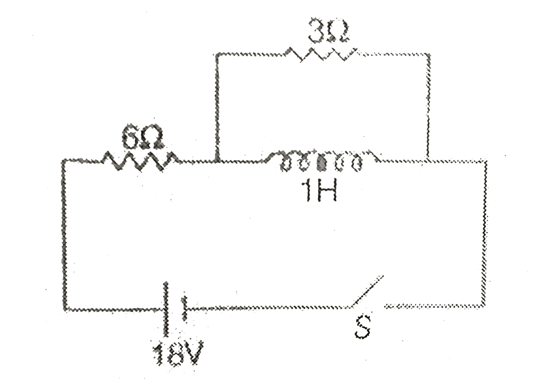
Current I from the battery at time t is given byView Solution

