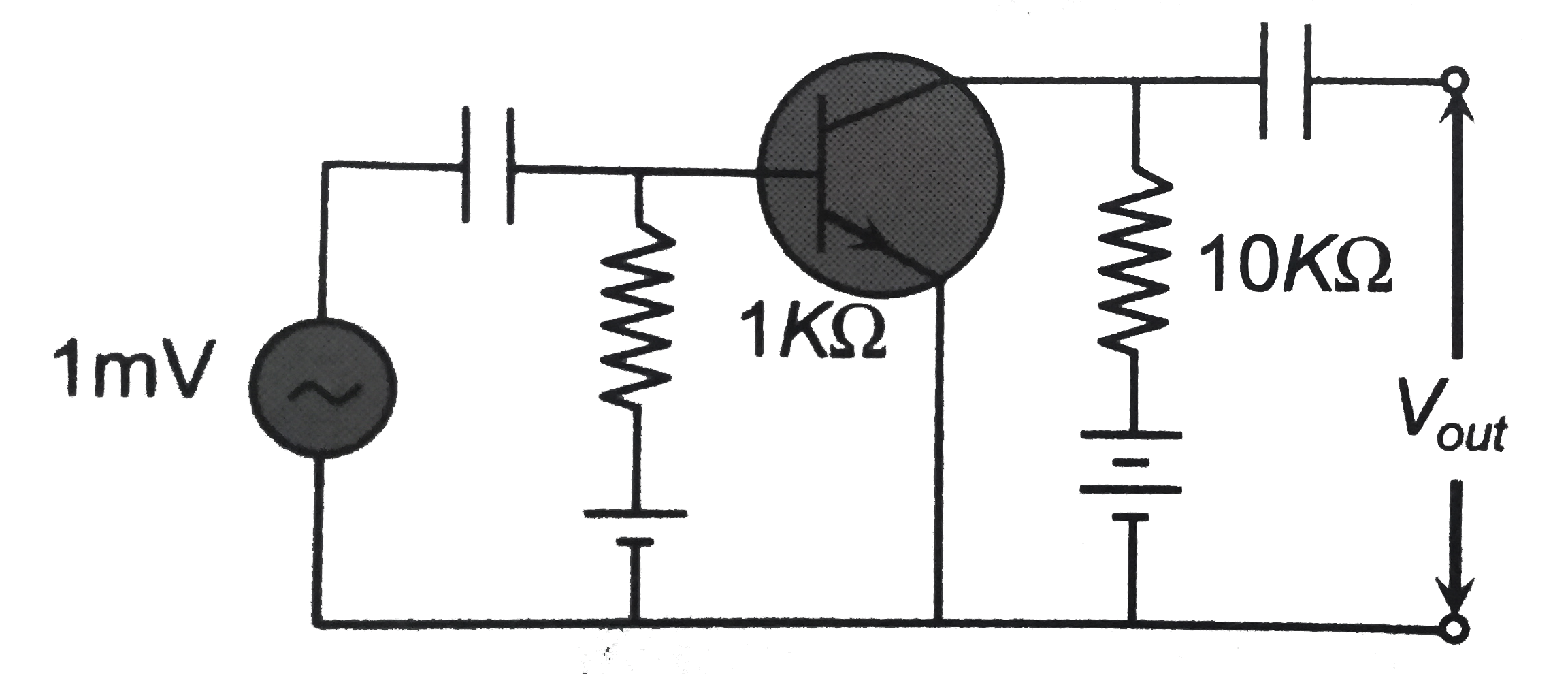
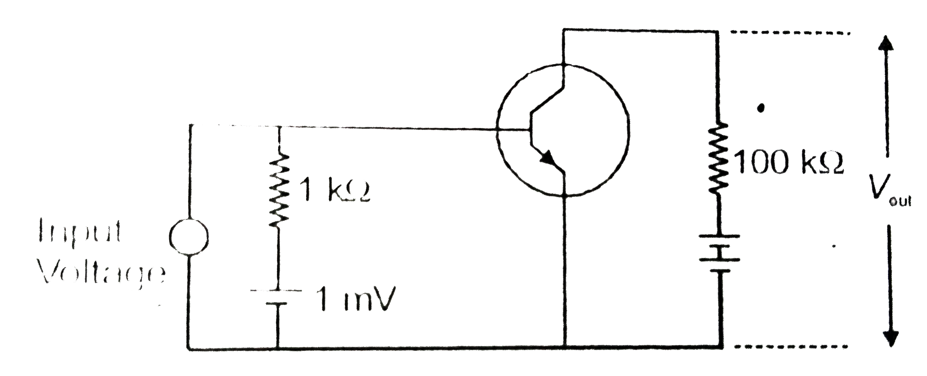
In which of the configuration of a transistor , the power gain is highest ?
Common base
Common emitter
Common collector
Same in all the three
The correct Answer is:B
To determine which configuration of a transistor provides the highest power gain, we can analyze the three common configurations: Common Base, Common Emitter, and Common Collector.
1. Understand the Transistor Configurations:
- Common Base (CB): The base terminal is common to both input and output. It has low input impedance and high output impedance.
- Common Emitter (CE): The emitter terminal is common to both input and output. It has high input impedance and moderate output impedance.
- Common Collector (CC): The collector terminal is common to both input and output. It has high input impedance and low output impedance.
2. Analyze Input and Output Impedance:
- The Common Emitter configuration has a high input impedance and a lower output impedance compared to the Common Base configuration. This allows for better voltage transfer and higher power gain.
3. Evaluate Voltage and Power Gain:
- The Common Emitter configuration is known for providing high voltage gain. Since power gain is a product of voltage gain and current gain, the high voltage gain in the Common Emitter configuration translates to high power gain as well.
4. Comparison with Other Configurations:
- The Common Base configuration typically has low voltage gain and, consequently, low power gain.
- The Common Collector configuration (also known as an emitter follower) provides good current gain but has a voltage gain of approximately 1, resulting in lower power gain compared to the Common Emitter.
5. Conclusion:
- Based on the analysis, the Common Emitter configuration provides the highest power gain among the three configurations.
Final Answer:
The configuration of a transistor in which the power gain is highest is the Common Emitter configuration.
- Common Base (CB): The base terminal is common to both input and output. It has low input impedance and high output impedance.
- Common Emitter (CE): The emitter terminal is common to both input and output. It has high input impedance and moderate output impedance.
- Common Collector (CC): The collector terminal is common to both input and output. It has high input impedance and low output impedance.
- The Common Emitter configuration has a high input impedance and a lower output impedance compared to the Common Base configuration. This allows for better voltage transfer and higher power gain.
- The Common Emitter configuration is known for providing high voltage gain. Since power gain is a product of voltage gain and current gain, the high voltage gain in the Common Emitter configuration translates to high power gain as well.
- The Common Base configuration typically has low voltage gain and, consequently, low power gain.
- The Common Collector configuration (also known as an emitter follower) provides good current gain but has a voltage gain of approximately 1, resulting in lower power gain compared to the Common Emitter.
- Based on the analysis, the Common Emitter configuration provides the highest power gain among the three configurations.
The configuration of a transistor in which the power gain is highest is the Common Emitter configuration.
Topper's Solved these Questions
- SEMICONDUCTOR ELECTRONICS: MATERIALS, DEVICES AND SIMPLE CIRCUITSBOOK - AAKASH INSTITUTE ENGLISHCHAPTER - SEMICONDUCTOR ELECTRONICS: MATERIALS, DEVICES AND SIMPLE CIRCUITSEXERCISE - Assignment (Section -C(Linked comprehension type question))
3 Videos
- SEMICONDUCTOR ELECTRONICS: MATERIALS, DEVICES AND SIMPLE CIRCUITSBOOK - AAKASH INSTITUTE ENGLISHCHAPTER - SEMICONDUCTOR ELECTRONICS: MATERIALS, DEVICES AND SIMPLE CIRCUITSEXERCISE - Assignment (Section-D (Assertion and reason))
5 Videos
- SEMICONDUCTOR ELECTRONICS: MATERIALS, DEVICES AND SIMPLE CIRCUITSBOOK - AAKASH INSTITUTE ENGLISHCHAPTER - SEMICONDUCTOR ELECTRONICS: MATERIALS, DEVICES AND SIMPLE CIRCUITSEXERCISE - Assignment (Section -A (Objective Type question (One option is correct))
50 Videos
- SEMICONDUCTOR ELECTRONICS (MATERIAL, DEVICES AND SIMPLE CIRUITS )BOOK - AAKASH INSTITUTE ENGLISHCHAPTER - SEMICONDUCTOR ELECTRONICS (MATERIAL, DEVICES AND SIMPLE CIRUITS )EXERCISE - Assignment SECTION - D (Assertion & reason type Question)
10 Videos
- SYSTEM OF PARTICLES AND ROTATIONAL MOTIONBOOK - AAKASH INSTITUTE ENGLISHCHAPTER - SYSTEM OF PARTICLES AND ROTATIONAL MOTIONEXERCISE - Try Yourself
63 Videos
Similar Questions
If α and β current gains in common-base and common-emitter configuration of a transistor, then β is equal to
View SolutionThe magnetic nature of elements depends on the presence of unpaired electrons. Identify the configuration of transition element, which shows highest magnetic moment.
View Solution
Knowledge Check
The magnetic nature of elements depends on the presence of unpaired electrons. Identify the configuration of transition element, which shows highest magnetic moment.
A3d7B3d5C3d8D3d2The magnetic nature of elements depends on the presence of unpaired electrons. Identify the configuration of transition element which shows highest magnetic moment.
A3d7B3d5C3d8D3d2For a transistor amplifier, the voltage gain
Aremains constant for all frequenciesBis high high and low frequencies and constant in the middle frequency rangeCis low at high and low frequencies and constant at mid frequenciesDnone of these
Among the following outermost configurations of transition metals, which shows the highest oxidation state
View SolutionIn the following common emitter configuration an NPN transistor with current gain β=100 is used. The output voltage of the amlifier will be

View SolutionIn the following common emitter configuration an NPN transistor with current gain β=100 is used. The output voltage of the amlifier will be

View SolutionIn the following common emitter configuration an n-p-n transistor with current gain β=100 is used. What is the output voltage of the amplifier ?

View SolutionIn a common-base configuration of a transistor ΔiΔie=0.98, then current gain in common emitter configuration of transistor will be
View Solution
