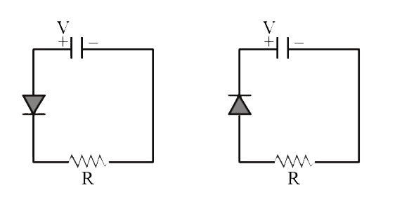
Two identical capacitors A and B are charged to the same potential V and are connected in two circuits at t=0 as shown in figure.The charges on the capacitor at a time t=CR are, respectively,
A. VC,VC
B. VC/e,VC
C. VC,VC/e
D. VC/e,VC/e
VC,VC
VC/e,VC
VC,VC/e
VC/e,VC/e
The correct Answer is:B
To solve the problem, we need to analyze the behavior of two identical capacitors A and B, which are charged to the same potential V and connected in two different circuits at time t=0.
1. Understand the Circuit Configuration:
- Capacitor A is connected in a circuit with a diode in forward bias, meaning the positive terminal of the capacitor is connected to the anode of the diode.
- Capacitor B is connected in a circuit with a diode in reverse bias, meaning the positive terminal of the capacitor is connected to the cathode of the diode.
2. Initial Charge on Capacitors:
- Both capacitors are initially charged to the same potential V. Therefore, the initial charge (Q) on each capacitor is given by:
Q=C×V
where C is the capacitance.
3. Behavior of Capacitor A (Forward Biased):
- In the forward bias condition, the diode allows current to flow. The voltage across the capacitor will decrease over time as it discharges through the resistor R.
- The voltage across the capacitor as a function of time (t) is given by:
V(t)=V0⋅e−t/(RC)
where V0=V.
4. Calculate Voltage at t = CR:
- Substitute t=CR into the voltage equation:
V(CR)=V⋅e−CR/(RC)=V⋅e−1=Ve
- The charge on capacitor A at this time is:
QA=C⋅V(CR)=C⋅Ve=CVe
5. Behavior of Capacitor B (Reverse Biased):
- In the reverse bias condition, the diode blocks current flow, effectively making the circuit open. Therefore, the charge on capacitor B remains unchanged.
- The charge on capacitor B at time t = CR is still:
QB=C⋅V=CV
6. Final Charges on Capacitors:
- At time t=CR:
- Charge on Capacitor A: QA=CVe
- Charge on Capacitor B: QB=CV
Conclusion:
The charges on the capacitors at time t=CR are:
- Capacitor A: CVe
- Capacitor B: CV
Thus, the correct answer is C. CV,CVe.
- Capacitor A is connected in a circuit with a diode in forward bias, meaning the positive terminal of the capacitor is connected to the anode of the diode.
- Capacitor B is connected in a circuit with a diode in reverse bias, meaning the positive terminal of the capacitor is connected to the cathode of the diode.
- Both capacitors are initially charged to the same potential V. Therefore, the initial charge (Q) on each capacitor is given by:
Q=C×V
where C is the capacitance.
- In the forward bias condition, the diode allows current to flow. The voltage across the capacitor will decrease over time as it discharges through the resistor R.
- The voltage across the capacitor as a function of time (t) is given by:
V(t)=V0⋅e−t/(RC)
where V0=V.
- Substitute t=CR into the voltage equation:
V(CR)=V⋅e−CR/(RC)=V⋅e−1=Ve
- The charge on capacitor A at this time is:
QA=C⋅V(CR)=C⋅Ve=CVe
- In the reverse bias condition, the diode blocks current flow, effectively making the circuit open. Therefore, the charge on capacitor B remains unchanged.
- The charge on capacitor B at time t = CR is still:
QB=C⋅V=CV
- At time t=CR:
- Charge on Capacitor A: QA=CVe
- Charge on Capacitor B: QB=CV
The charges on the capacitors at time t=CR are:
- Capacitor A: CVe
- Capacitor B: CV
Topper's Solved these Questions
- SEMICONDUCTOR ELECTRONICS: MATERIALS, DEVICES AND SIMPLE CIRCUITSBOOK - AAKASH INSTITUTE ENGLISHCHAPTER - SEMICONDUCTOR ELECTRONICS: MATERIALS, DEVICES AND SIMPLE CIRCUITSEXERCISE - Assignment (Section -C(Linked comprehension type question))
3 Videos
- SEMICONDUCTOR ELECTRONICS: MATERIALS, DEVICES AND SIMPLE CIRCUITSBOOK - AAKASH INSTITUTE ENGLISHCHAPTER - SEMICONDUCTOR ELECTRONICS: MATERIALS, DEVICES AND SIMPLE CIRCUITSEXERCISE - Assignment (Section-D (Assertion and reason))
5 Videos
- SEMICONDUCTOR ELECTRONICS: MATERIALS, DEVICES AND SIMPLE CIRCUITSBOOK - AAKASH INSTITUTE ENGLISHCHAPTER - SEMICONDUCTOR ELECTRONICS: MATERIALS, DEVICES AND SIMPLE CIRCUITSEXERCISE - Assignment (Section -A (Objective Type question (One option is correct))
50 Videos
- SEMICONDUCTOR ELECTRONICS (MATERIAL, DEVICES AND SIMPLE CIRUITS )BOOK - AAKASH INSTITUTE ENGLISHCHAPTER - SEMICONDUCTOR ELECTRONICS (MATERIAL, DEVICES AND SIMPLE CIRUITS )EXERCISE - Assignment SECTION - D (Assertion & reason type Question)
10 Videos
- SYSTEM OF PARTICLES AND ROTATIONAL MOTIONBOOK - AAKASH INSTITUTE ENGLISHCHAPTER - SYSTEM OF PARTICLES AND ROTATIONAL MOTIONEXERCISE - Try Yourself
63 Videos
Similar Questions
Two identical capacitors A and B are charged to the same potential V and are connected in two circuits at t = 0 as shown in figure. The charge of the capacitors at a time t = CR are respectively -
View SolutionThree capacitors A,B and C are connected in a circuit as shown in figure. What is the charge in μC on the capacitor B?
View Solution
Knowledge Check
Two idential capacitors are joined in parallel, charged to a potential V and then separated and then connected in series i.e. the positive plate of one is connected to negative of the other
AThe charges on the free plated connected together are destoyed.BThe energy stored in the system increases.CThe potential difference between the free plates is 2V.DThe potential difference remains constant.
Three capacitor A,B, and C, are connected in a circuit as shown in. What is the charge in μC on the capacitor B?
 .
.
View SolutionTwo identical capacitor A and B, charged to the same potential 5V are connected in two different circuits as shown below at time t=0. t=CR is QAandQB respectively, then (Here e is the base of natureal logarithm)
View SolutionTwo identical capacitors A and B are charged to the same potential and then made to discharge through resistances RA and RB respectively, with RA>RB.
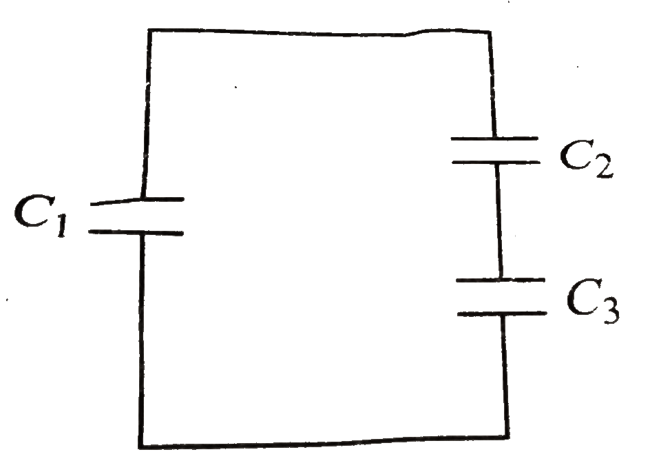
View SolutionCapacitor C1 is connected to a battery and charged till the magnitude of the charge on each plate is q0. Then, the battery is disconnected and C1 is connected to two other uncharged capacitors C2andC3 as shown in figure. Final charges on the capacitors (q1,q2andq3) are related by .
View SolutionTwo capacitors C1 and C2 are charged to same potential V, but with opposite polarity as shown in the figure. The switches S1 and S2 are then closed

View SolutionTwo capacitors A and B are connected in series with a battery as shown in the figure. When the switch S is closed and the two capacitors get charged fully, then
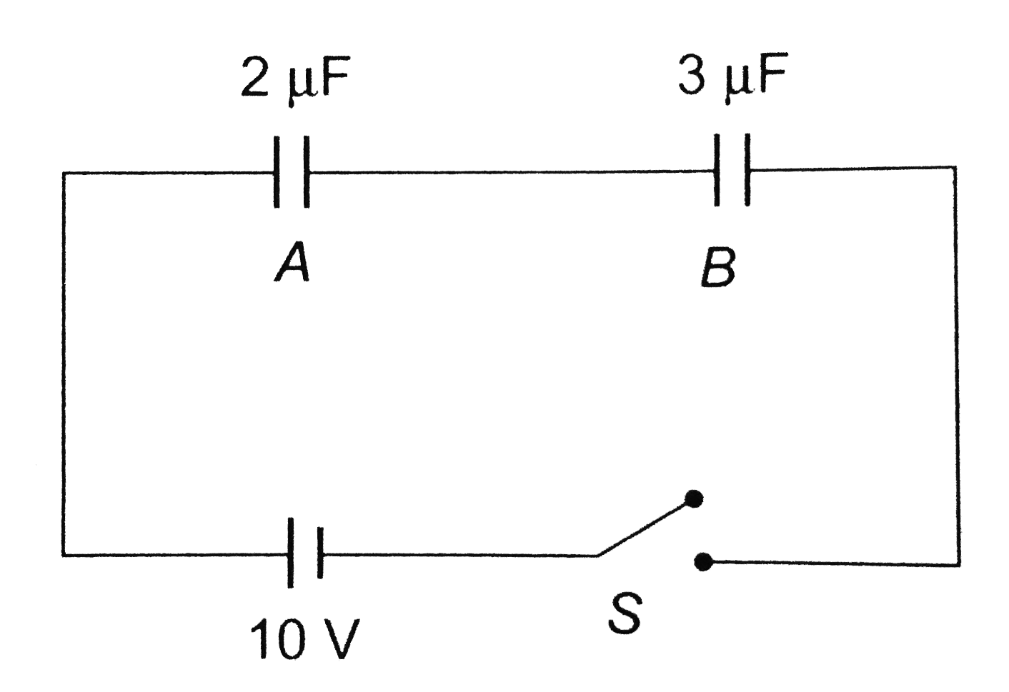
View SolutionTwo capacitors A and B are connected in series with a battery as shown in the figure. When the switch S is closed and the two capacitors get charged fully, then

View Solution
