In the given circuit , the voltage across the base emitter junction is
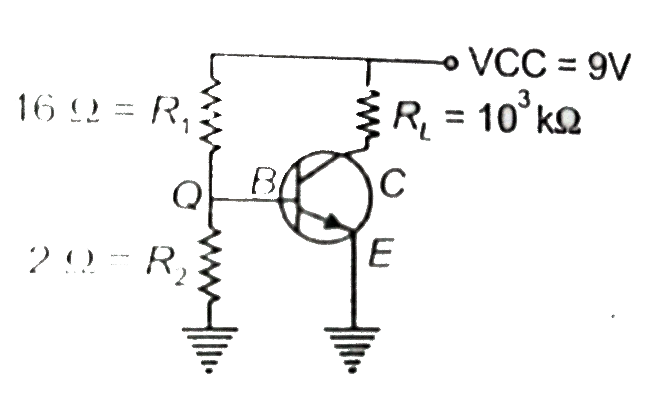
2V
1V
3V
4V
The correct Answer is:B
Step by step video & image solution for In the given circuit , the voltage across the base emitter junction is by Physics experts to help you in doubts & scoring excellent marks in Class 12 exams.
Updated on:21/07/2023Topper's Solved these Questions
- SEMICONDUCTOR ELECTRONICS: MATERIALS, DEVICES AND SIMPLE CIRCUITSBOOK - AAKASH INSTITUTE ENGLISHCHAPTER - SEMICONDUCTOR ELECTRONICS: MATERIALS, DEVICES AND SIMPLE CIRCUITSEXERCISE - Assignment (Section -C(Linked comprehension type question))
3 Videos
- SEMICONDUCTOR ELECTRONICS: MATERIALS, DEVICES AND SIMPLE CIRCUITSBOOK - AAKASH INSTITUTE ENGLISHCHAPTER - SEMICONDUCTOR ELECTRONICS: MATERIALS, DEVICES AND SIMPLE CIRCUITSEXERCISE - Assignment (Section-D (Assertion and reason))
5 Videos
- SEMICONDUCTOR ELECTRONICS: MATERIALS, DEVICES AND SIMPLE CIRCUITSBOOK - AAKASH INSTITUTE ENGLISHCHAPTER - SEMICONDUCTOR ELECTRONICS: MATERIALS, DEVICES AND SIMPLE CIRCUITSEXERCISE - Assignment (Section -A (Objective Type question (One option is correct))
50 Videos
- SEMICONDUCTOR ELECTRONICS (MATERIAL, DEVICES AND SIMPLE CIRUITS )BOOK - AAKASH INSTITUTE ENGLISHCHAPTER - SEMICONDUCTOR ELECTRONICS (MATERIAL, DEVICES AND SIMPLE CIRUITS )EXERCISE - Assignment SECTION - D (Assertion & reason type Question)
10 Videos
- SYSTEM OF PARTICLES AND ROTATIONAL MOTIONBOOK - AAKASH INSTITUTE ENGLISHCHAPTER - SYSTEM OF PARTICLES AND ROTATIONAL MOTIONEXERCISE - Try Yourself
63 Videos
Similar Questions
In the given circuit, the voltage across the load is maintained at 12 V. The current in the zener diode varies from 0.51 mA. What is the maximum wattage of the diode?

View SolutionIn the given circuit the voltage drop across the diode is 0.8 V, if the diode can withstand current upto maximum of 30 mA, then find the maximum voltage of the battery
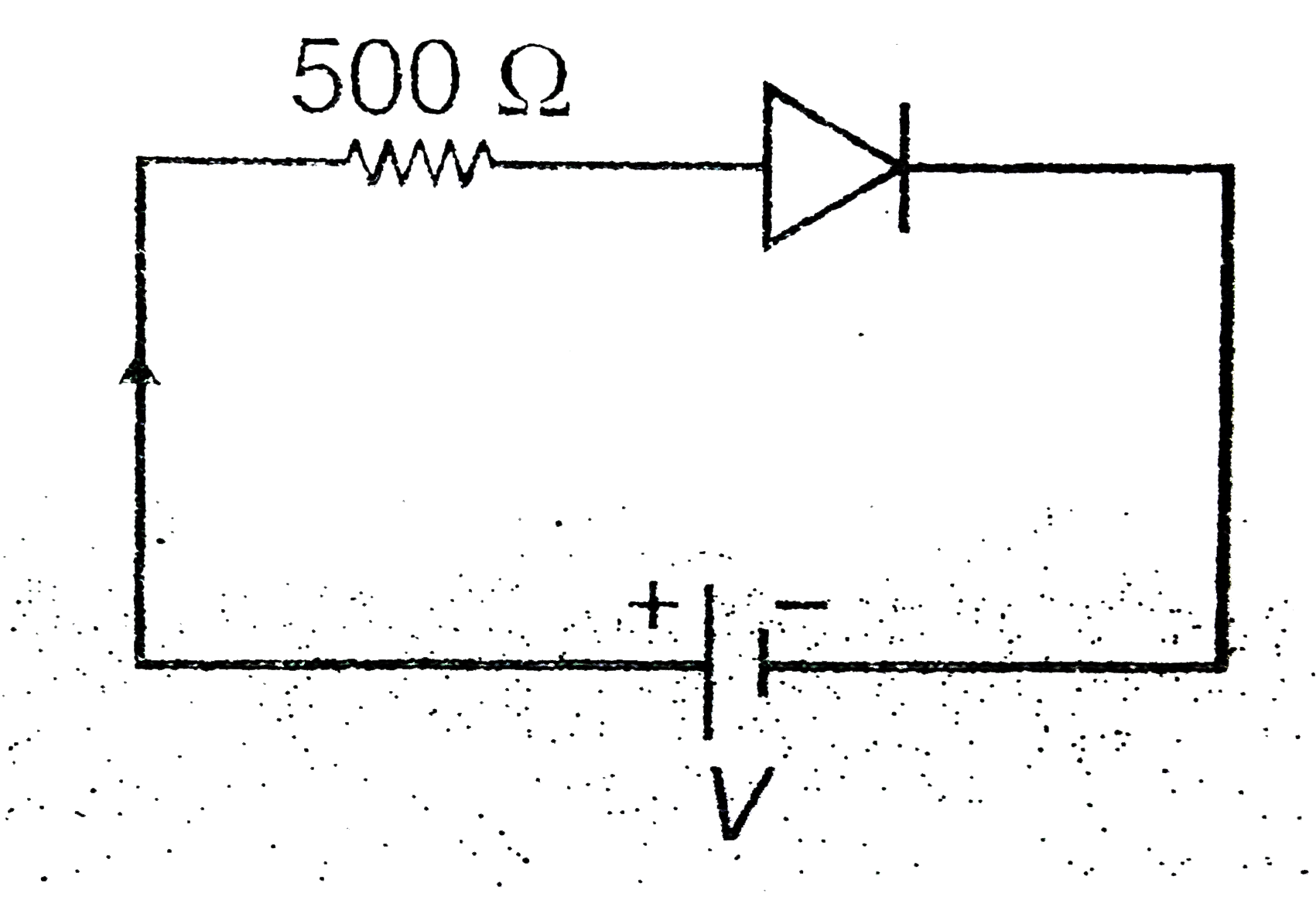
View Solution
Knowledge Check
In a series LCR circuit, the voltage across the resistance, capacitance and inductance is 10 V each. If the capacitance is short circuited, the voltage across the inductance will be
A10VB10√2VC10√2VD20V
Assertion : In transistor common emitter mode as an amplifier is prefered over common base mode.
Reason: In common emitter mode the input signal is connected in series with the voltage applied to the base emitter function.
View SolutionA transistor is used in common emitter mode as an amplifier. Then
(1) the base-emitter junction is forward biased
(2) the base emitter junction is reverse biased
(3) the input signal is connected in series with the voltage applied to the base-emitter junction.
(4) the input signal is connected in series with the voltage applied to the base collector junction.
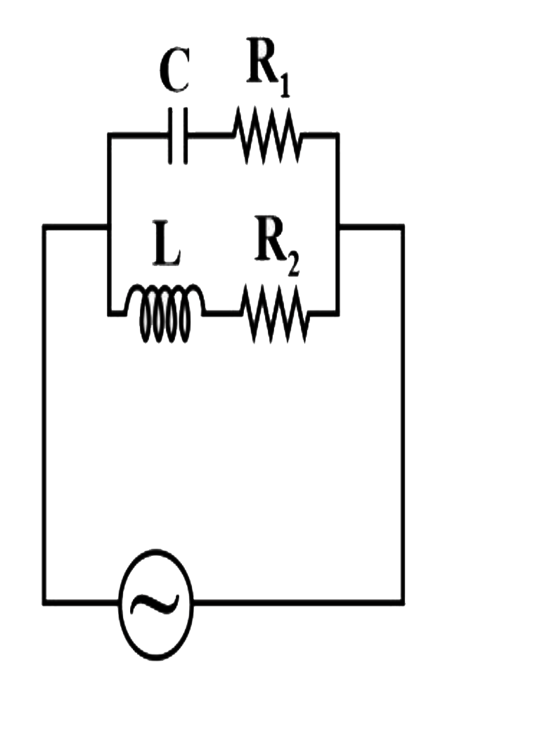
View SolutionIn the given circuit the R.M.S values of voltages across the capacitor C, inductor L and resistor R1 are 12V, 10V and 5 V respectively. Then the peak voltage across R2 is
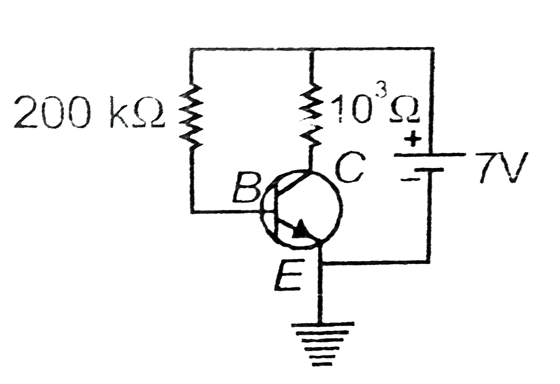
View SolutionIn the given figure, a transistor is connected in common emitter configuration . If VBE=1V and current gain β=100, then the voltage across collector- emitter terminals VCE is
[VBE-voltage across base-emitter junction ]
View SolutionIn an LCR series ac circuit , the voltage across each of the components , L,C and R is 50 V . The voltage across the LC combination will be :
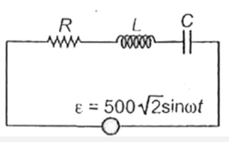
View SolutionIn a series RLC circuit the r.m.s. voltage across the resistor and the inductor are respectively 400 V and 700 V. If the equation for the applied Voltage is ε=500√2sinωt. then the peak voltage across the capacitor is
View SolutionIn a series L-C-R circuit the voltage across resistance , capacitance and inductance is 10 V each. If the capacitance is short circuited, the voltage across the inductance will be
View Solution
