In the adder circuits of two inputs
AND gate is used for carry forward memory
XOR gate is used for display
Both (1) and (2)
none of these
The correct Answer is:C
To solve the question regarding the adder circuits of two inputs, we will analyze the half adder circuit, which consists of an AND gate and an XOR gate. Here’s a step-by-step solution:
1. Understanding the Half Adder:
- A half adder is a circuit that adds two single binary digits (bits) and produces a sum and a carry output.
- The two inputs are typically denoted as A and B.
2. Identifying the Gates Used:
- The half adder uses two types of logic gates:
- XOR Gate: This gate is used to calculate the sum (S) of the two inputs.
- AND Gate: This gate is used to calculate the carry (C) from the addition.
3. Writing the Output Expressions:
- The output of the XOR gate, which gives the sum (S), can be expressed as:
S=A⊕B=AB′+A′B
- The output of the AND gate, which gives the carry (C), can be expressed as:
C=A⋅B
4. Conclusion:
- In summary, for a half adder:
- The sum (S) is produced by the XOR gate.
- The carry (C) is produced by the AND gate.
- Therefore, both the expressions for sum and carry are valid.
5. Selecting the Correct Options:
- If the question provides multiple options regarding the outputs of the half adder, the correct options would include:
- The expression for the sum (S) and the expression for the carry (C).
- Hence, if options A and B correspond to these outputs, then both are correct.
Final Answer:
Both options A and B are correct regarding the outputs of the half adder circuit.
---
- A half adder is a circuit that adds two single binary digits (bits) and produces a sum and a carry output.
- The two inputs are typically denoted as A and B.
- The half adder uses two types of logic gates:
- XOR Gate: This gate is used to calculate the sum (S) of the two inputs.
- AND Gate: This gate is used to calculate the carry (C) from the addition.
- The output of the XOR gate, which gives the sum (S), can be expressed as:
S=A⊕B=AB′+A′B
- The output of the AND gate, which gives the carry (C), can be expressed as:
C=A⋅B
- In summary, for a half adder:
- The sum (S) is produced by the XOR gate.
- The carry (C) is produced by the AND gate.
- Therefore, both the expressions for sum and carry are valid.
- If the question provides multiple options regarding the outputs of the half adder, the correct options would include:
- The expression for the sum (S) and the expression for the carry (C).
- Hence, if options A and B correspond to these outputs, then both are correct.
Both options A and B are correct regarding the outputs of the half adder circuit.
Topper's Solved these Questions
- SEMICONDUCTOR ELECTRONICS: MATERIALS, DEVICES AND SIMPLE CIRCUITSBook:AAKASH INSTITUTE ENGLISHChapter:SEMICONDUCTOR ELECTRONICS: MATERIALS, DEVICES AND SIMPLE CIRCUITSExercise:Assignment (Section -C(Linked comprehension type question))
Explore 3 Videos
- SEMICONDUCTOR ELECTRONICS: MATERIALS, DEVICES AND SIMPLE CIRCUITSBook:AAKASH INSTITUTE ENGLISHChapter:SEMICONDUCTOR ELECTRONICS: MATERIALS, DEVICES AND SIMPLE CIRCUITSExercise:Assignment (Section-D (Assertion and reason))
Explore 5 Videos
- SEMICONDUCTOR ELECTRONICS: MATERIALS, DEVICES AND SIMPLE CIRCUITSBook:AAKASH INSTITUTE ENGLISHChapter:SEMICONDUCTOR ELECTRONICS: MATERIALS, DEVICES AND SIMPLE CIRCUITSExercise:Assignment (Section -A (Objective Type question (One option is correct))
Explore 50 Videos
- SEMICONDUCTOR ELECTRONICS (MATERIAL, DEVICES AND SIMPLE CIRUITS )Book:AAKASH INSTITUTE ENGLISHChapter:SEMICONDUCTOR ELECTRONICS (MATERIAL, DEVICES AND SIMPLE CIRUITS )Exercise:Assignment SECTION - D (Assertion & reason type Question)
Explore 10 Videos
- SYSTEM OF PARTICLES AND ROTATIONAL MOTIONBook:AAKASH INSTITUTE ENGLISHChapter:SYSTEM OF PARTICLES AND ROTATIONAL MOTIONExercise:Try Yourself
Explore 63 Videos
Similar Questions
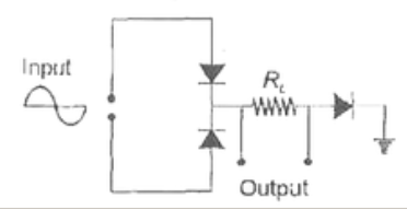
In the circuit shown , the input waveform is given. Which of the following correctly gives the output wavefrorm across RL?
View SolutionThe following figure shows a logic gate circuit with two inputs A and B and the output C. The voltage waveforms of A, B and C are as given The logic circuit is:
View Solution
Knowledge Check
The following figure shows a logic gate circuit with two inputs A and B and the output Y. The voltage waveforms of A,B and Y are as given :
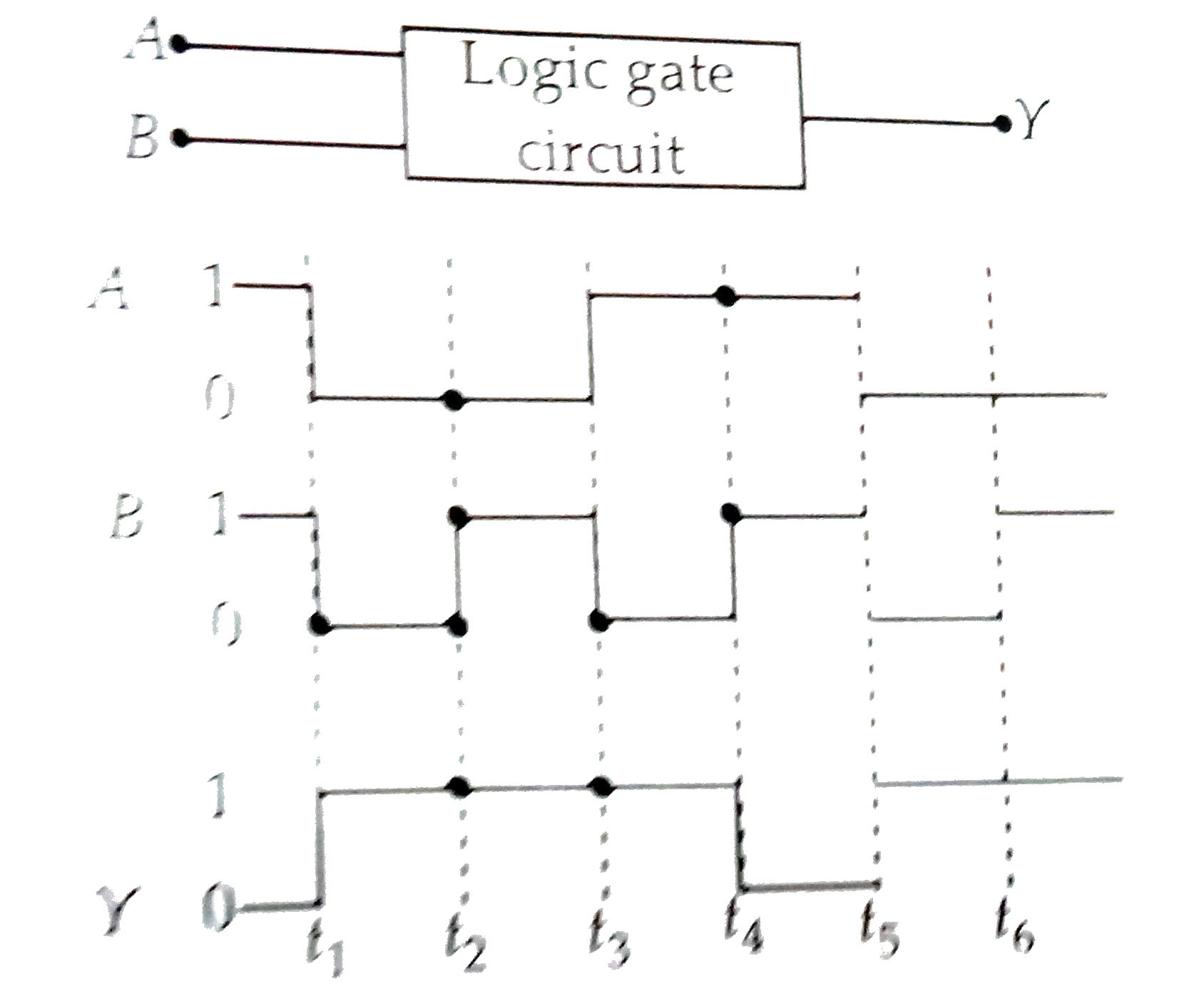
The logic gate isANOR gateBOR gateCAND gateDNAND gate
The following figure shows a logic gate circuit with two inputs A and B output C. The voltage waveforms of A,B and C are as shown in second figure given below :-
_E01_436_Q01.png)
The logic circuit gate is :-
View SolutionWhen the inputs of a two input logic gate are 0 and 0, the output is 1. When the inputs are 1 and 0, the output is zero. The type of logic gate is
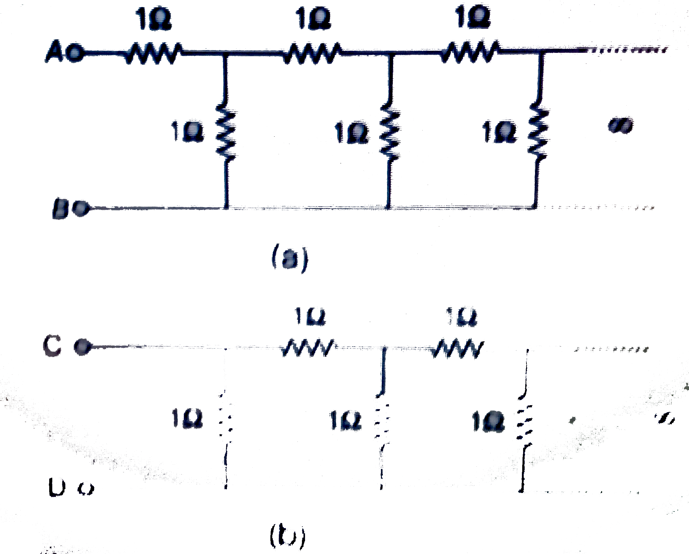
View SolutionIn the two circuits shown in figure
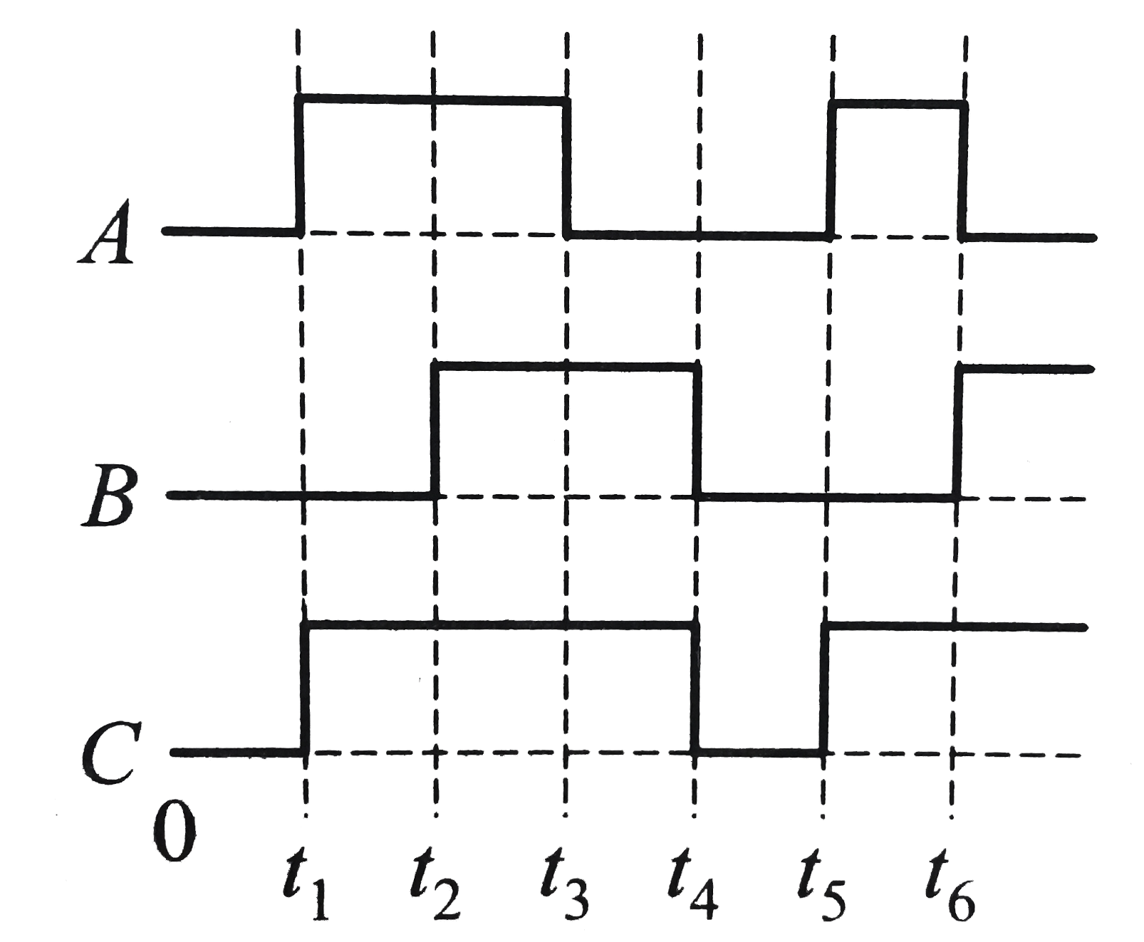
View SolutionThe figure shows a logic circuit with two inputs A and B and the output C. The voltage wave forms across A,B and C are as given. The logic circuit gate is
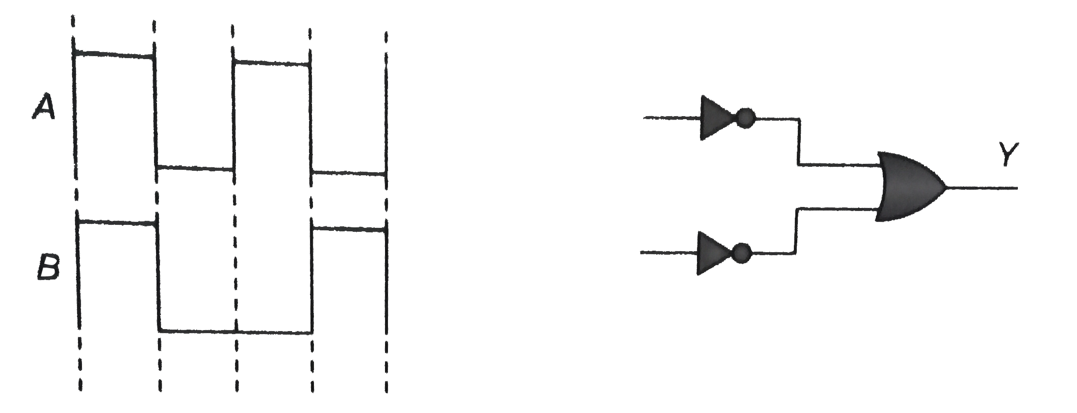
View SolutionIn the given circuit as shown the two input waveform A and B are applied simultaneously. The resultant waveform Y is
View Solution(i) Write the functions of three segments of a transistor.
(ii) Draw the ciruit diagram or studying the input and output characteristics of n-p-n transisfor in common emitter configuration . Using the circuit explain how input characteristics are obtained .
View SolutionUsing the wave forms of the input A and B, draw the output waveform of the given logic circuit . Identify the logic gate obtained . Write also the truth table.

View Solution