In the circuit shown in the figure , the resistance marked R can be varied by using a Rheostat. The power across the 5 Omega resistor will be maximum if the Rhoestat has resistance equal to
_PHY_E01_015_Q01.png)
5 Ω
20 Ω
10 Ω
Zero
Step by step video & image solution for In the circuit shown in the figure , the resistance marked R can be varied by using a Rheostat. The power across the 5 Omega resistor will be maximum if the Rhoestat has resistance equal to by Physics experts to help you in doubts & scoring excellent marks in Class 12 exams.
Updated on:21/07/2023Topper's Solved these Questions
- TEST 1BOOK - AAKASH INSTITUTE ENGLISHCHAPTER - TEST 1EXERCISE - EXERCISE
21 Videos
- SYSTEM OF PARTICLES AND ROTATIONAL MOTIONBOOK - AAKASH INSTITUTE ENGLISHCHAPTER - SYSTEM OF PARTICLES AND ROTATIONAL MOTIONEXERCISE - Try Yourself
63 Videos
- TEST 2BOOK - AAKASH INSTITUTE ENGLISHCHAPTER - TEST 2EXERCISE - Exercise
308 Videos
Similar Questions
In the circuit shown in figure resistance of each wire is r. Net resistance across

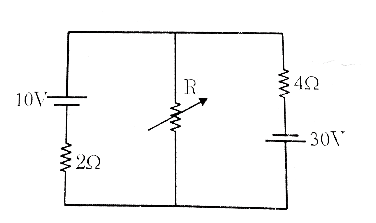
View SolutionIn the circuit shown in the figure, the value of maximum rate of heat production in resistance R is
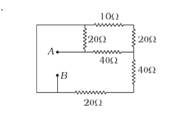
View SolutionIn the circuit shown in figure, the equivalent resistance between A and B is __________ Ω.
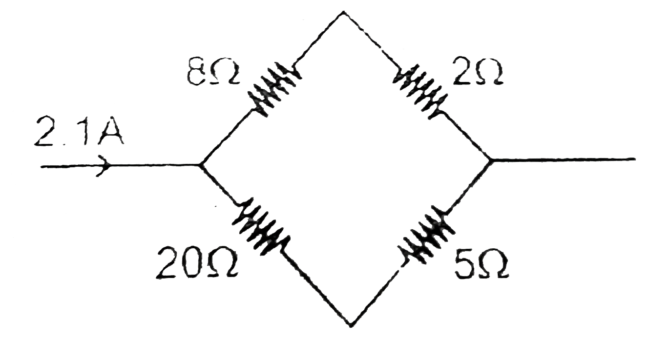
View SolutionIn the circuit in figure, the current flowing 5Ω resistance is :
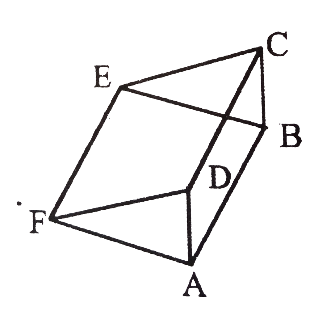
View SolutionIn the circuit shown in figure, all wires have equal resistance r. Find the equivalent resistance between A and B
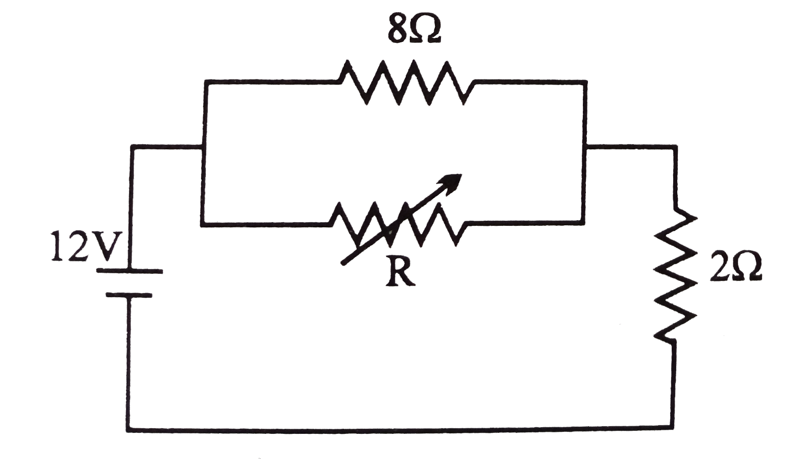
View SolutionThe value of the resistance R in figure is adjusted such that power dissipated in the 2Ω resistor is maximum. Under this condition
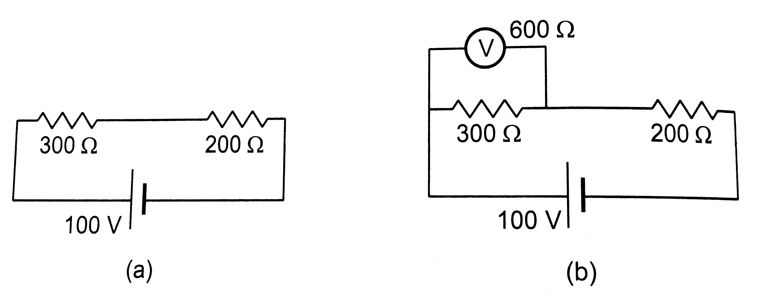
View Solution(a)find the potential drops across the two resistors shown in figure. (b) A voltmeter of resistance (600Ω)is used to measure the potential drop across the (300Ω) resistor.What will be the measured potential drop?
View SolutionIf the power dissipated in the 27Ω resistor in the circuit shown is 108 watt, the potential difference across the 4Ω resistor is
View SolutionFor the circuit shown in figure, determine the voltage across 4Ω resistors in volt ?

View SolutionConsider the circuit shown in figure.Find (a) the current in the circuit, (b) the potential drop across the (5Ω)resistor,(c )the potential drop across the 10(Ω)resistor.(d)Answer the parts (a),(b)and (c )with reference to figure.

View Solution

