The equivalent capacitance of the circuit as shown in figure between points A and B is _PHY_E01_019_Q01.png)
10μF
8μF
2μF
15μF
Step by step video & image solution for The equivalent capacitance of the circuit as shown in figure between points A and B is by Physics experts to help you in doubts & scoring excellent marks in Class 12 exams.
Updated on:21/07/2023Topper's Solved these Questions
- TEST 1BOOK - AAKASH INSTITUTE ENGLISHCHAPTER - TEST 1EXERCISE - EXERCISE
21 Videos
- SYSTEM OF PARTICLES AND ROTATIONAL MOTIONBOOK - AAKASH INSTITUTE ENGLISHCHAPTER - SYSTEM OF PARTICLES AND ROTATIONAL MOTIONEXERCISE - Try Yourself
63 Videos
- TEST 2BOOK - AAKASH INSTITUTE ENGLISHCHAPTER - TEST 2EXERCISE - Exercise
308 Videos
Similar Questions
Knowledge Check
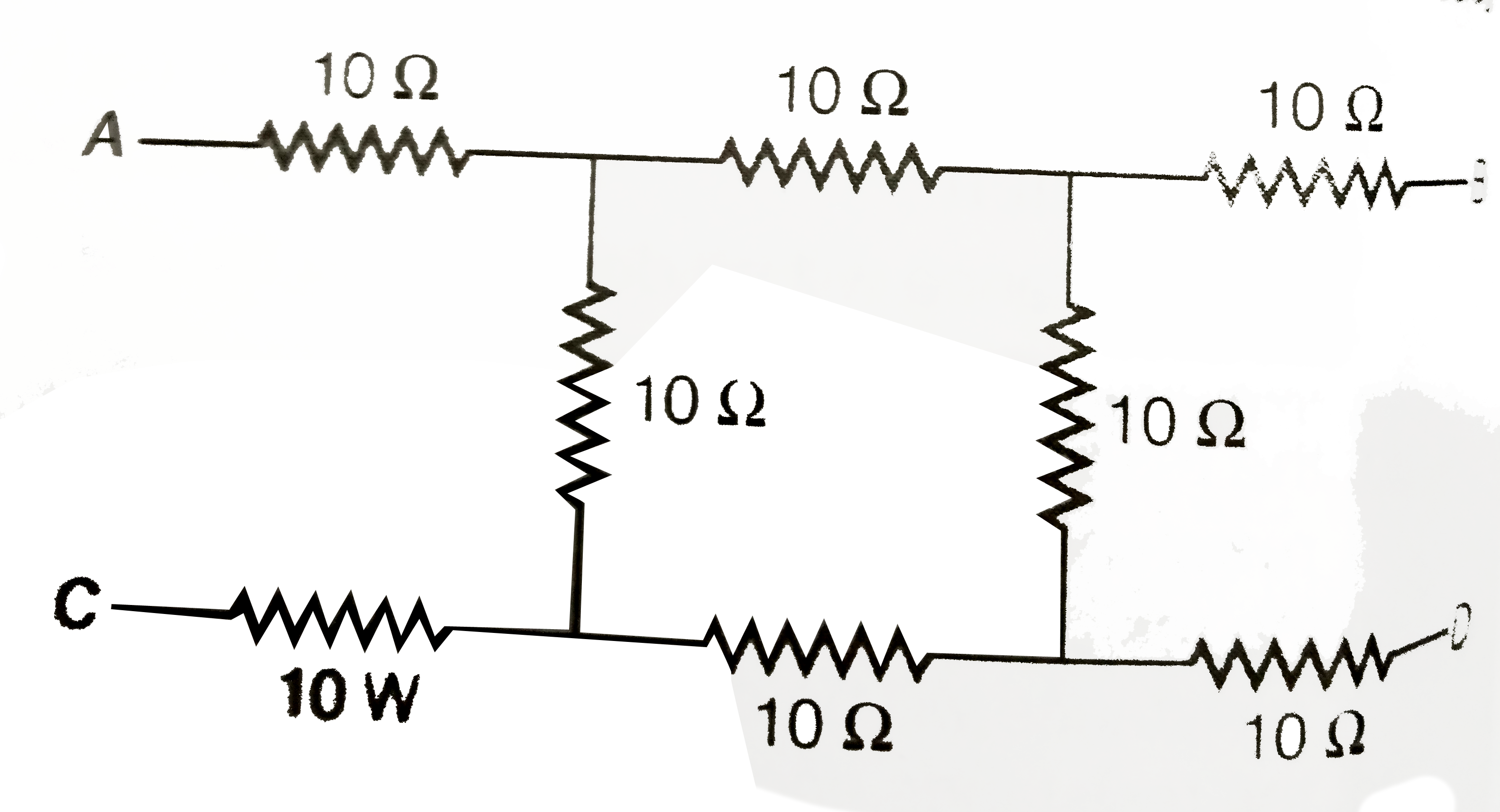
The equivalent resistance of the circuit shown in figure between the points A and B if VA<VB is
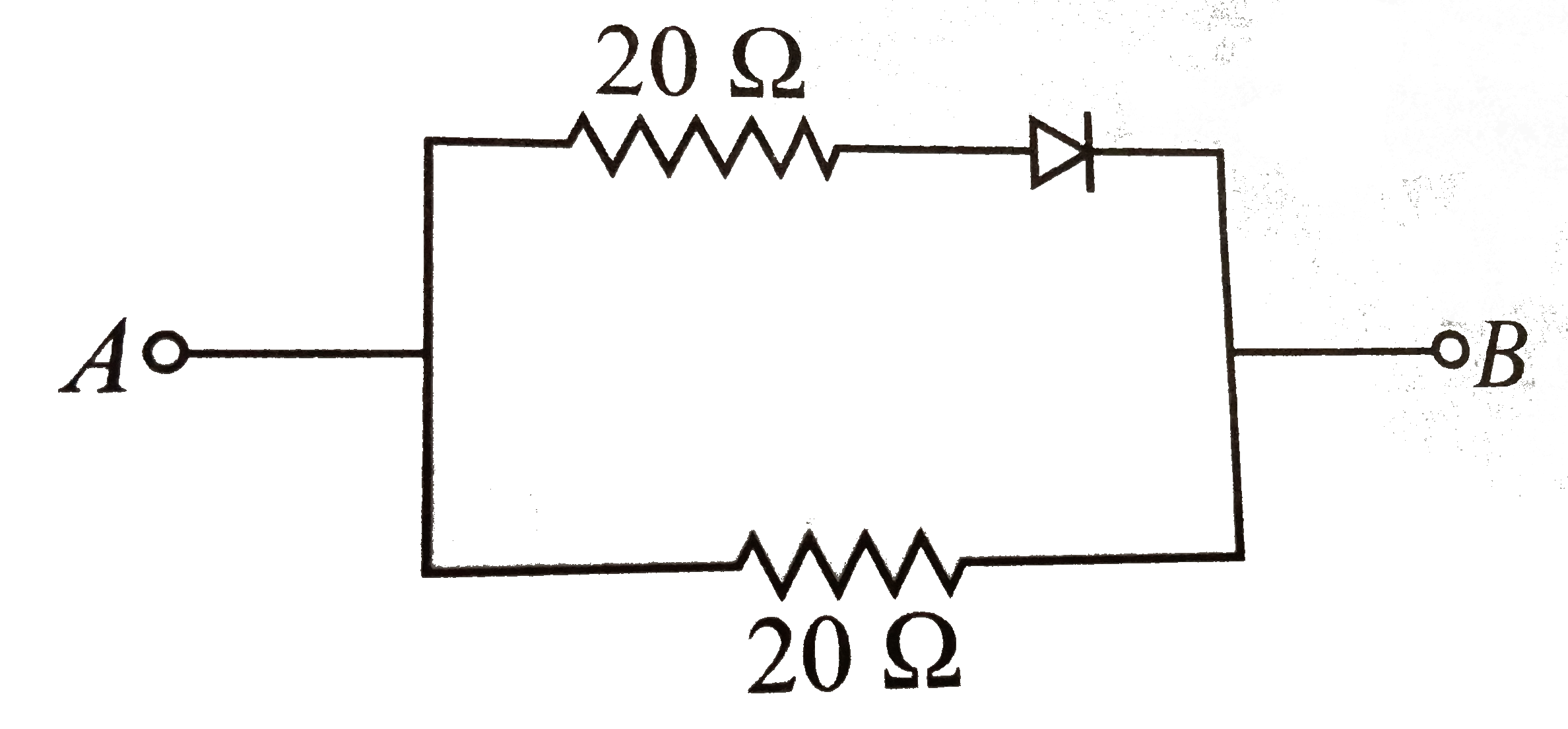 A10ΩB20ΩC5ΩD40Ω
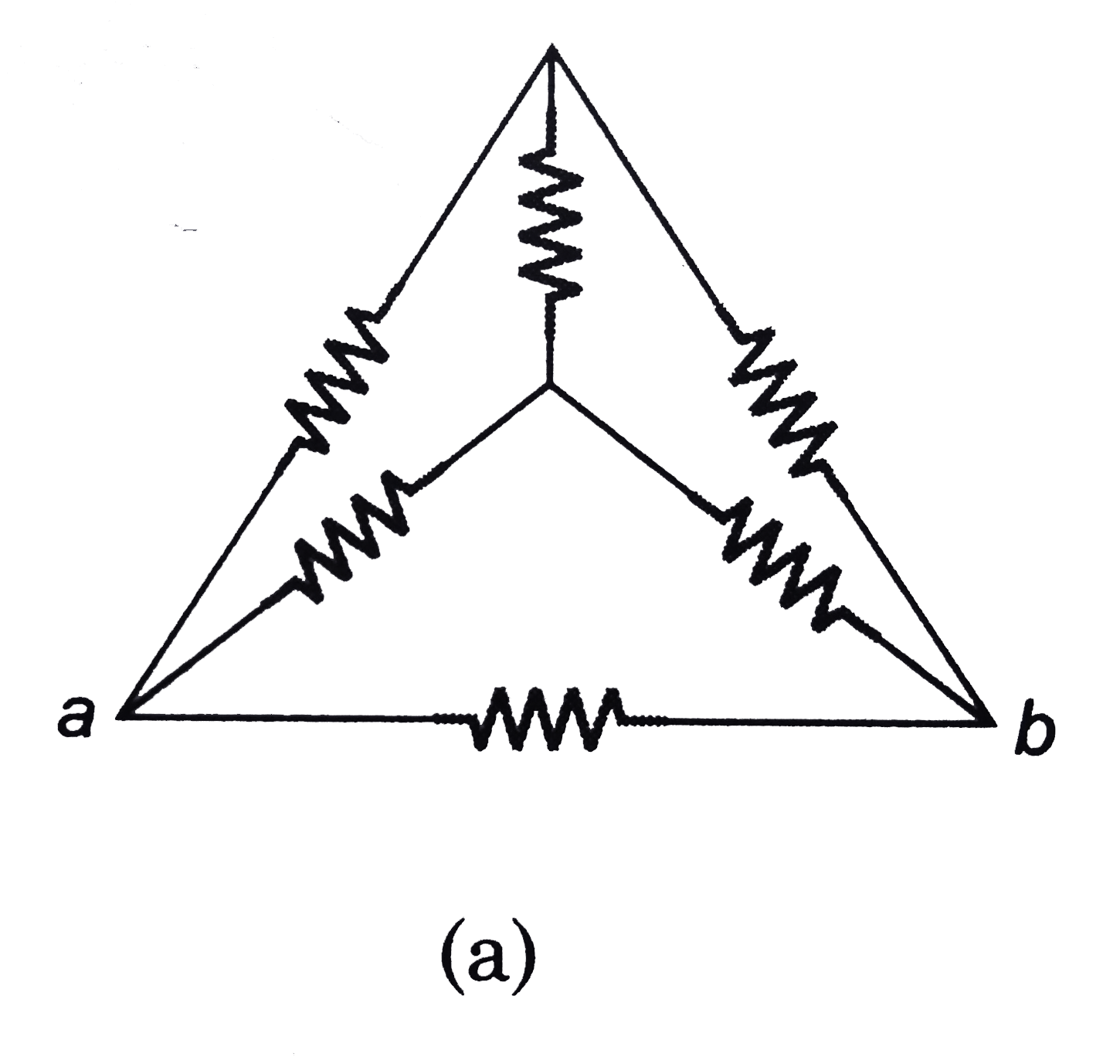
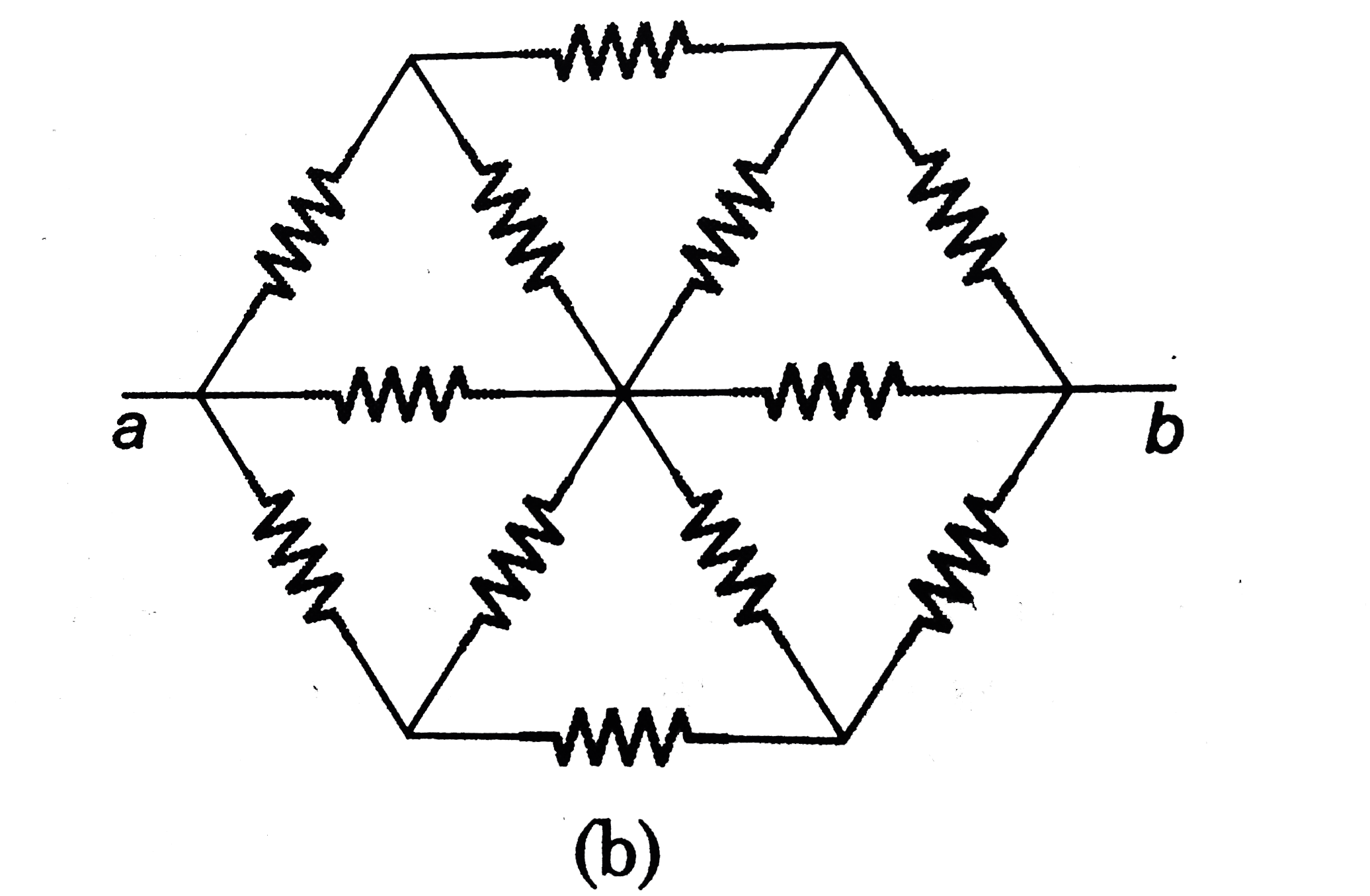
Find the equivalent resistance of the circuits shown in figure between the points a and b. Each resistor has a resistance r.
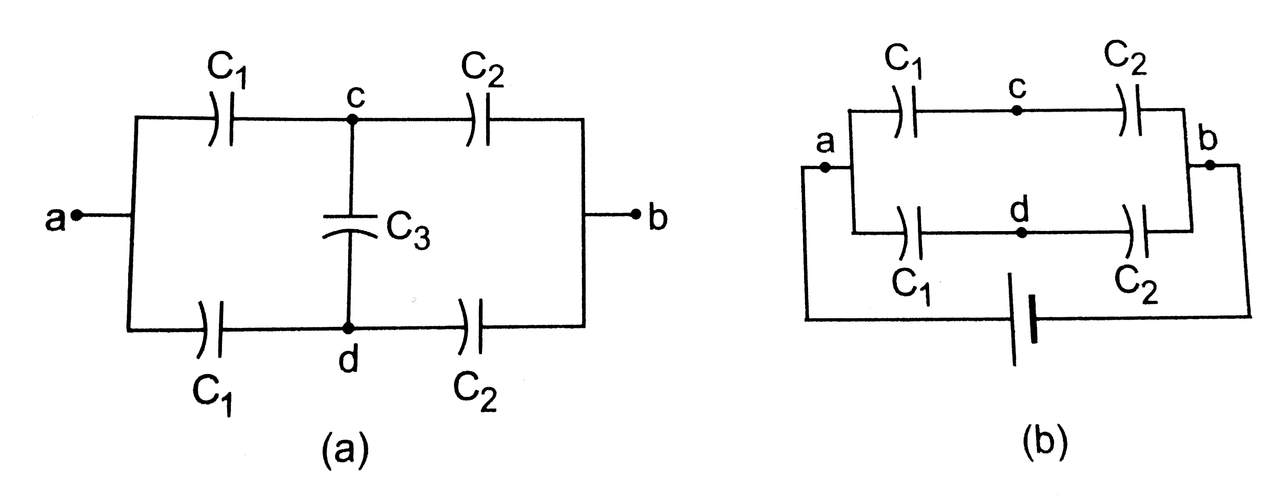
View SolutionFind the equivalent capacitance of the system shown in figure between the points a and b.
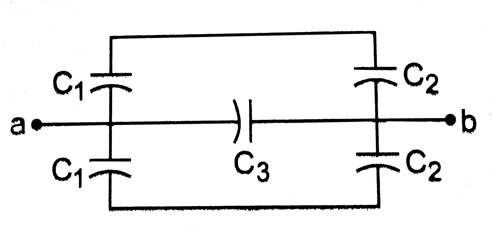
View SolutionFind the equivalent capacitance of the system shown in figure between the points a and b .
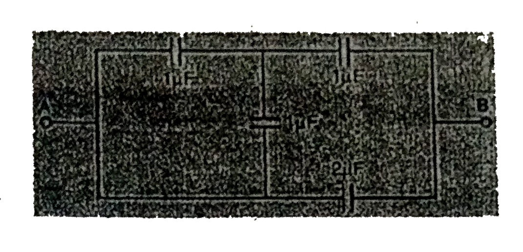
View SolutionThe equivalent capacitance of the circuit shown, between points A and B will be-
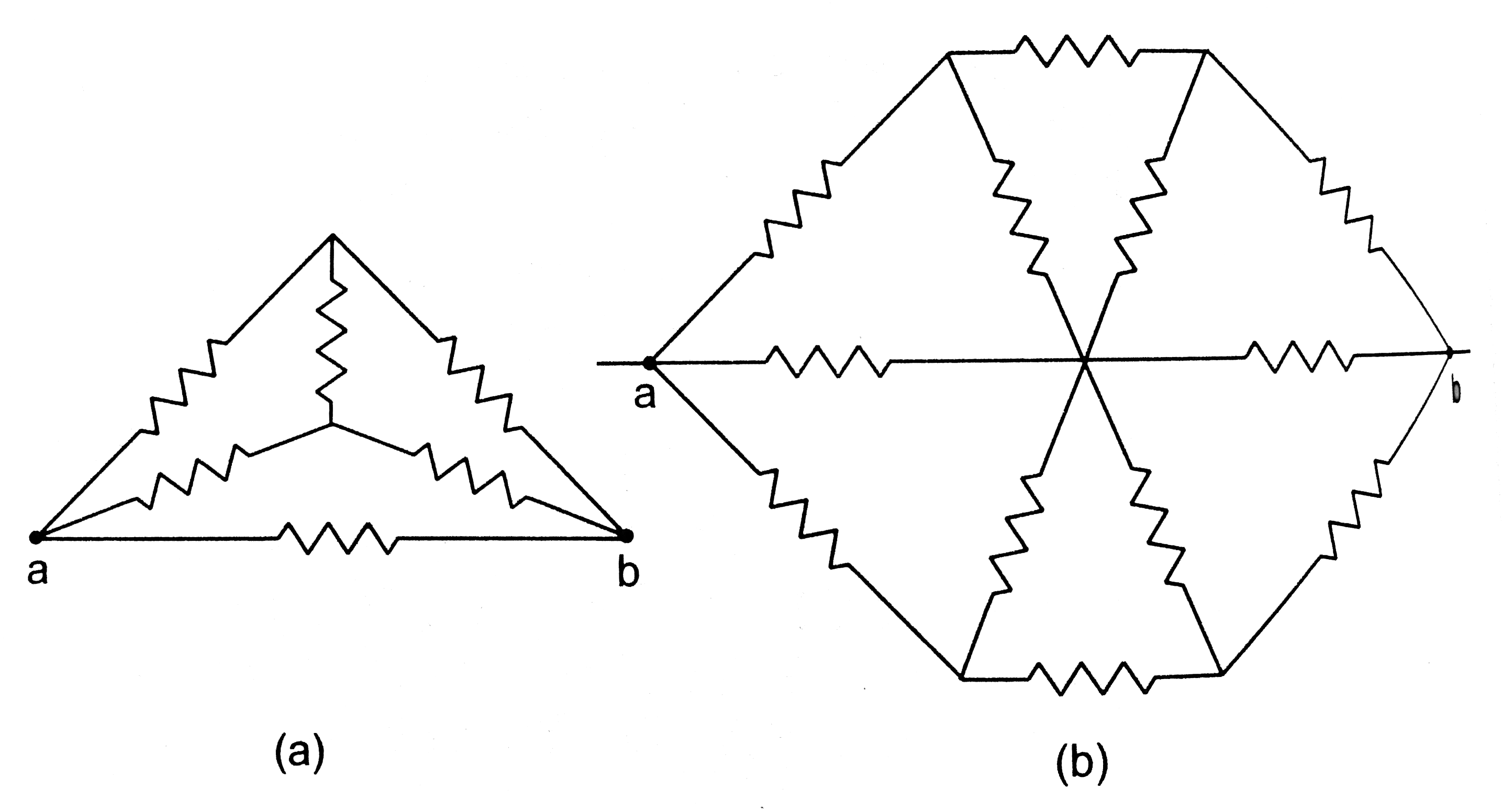
View SolutionFind the equivalent resistance of the circuit shown in figure between the points a and b.Each resistor has a resistances r.
View SolutionCalculate the charge on equivalent capacitance of the combination shown in figure between the points P and N.

View SolutionWhat will be the equivalent resistance fo circuit shown in figure between two points A and D?
View Solution
