In the circuit shown in figure: R1=10Ω,L+√310H,R2=20ΩandC−√32mF. Current in L−R1circuit isI1inC−R2circuit isI2 and the main current is I.
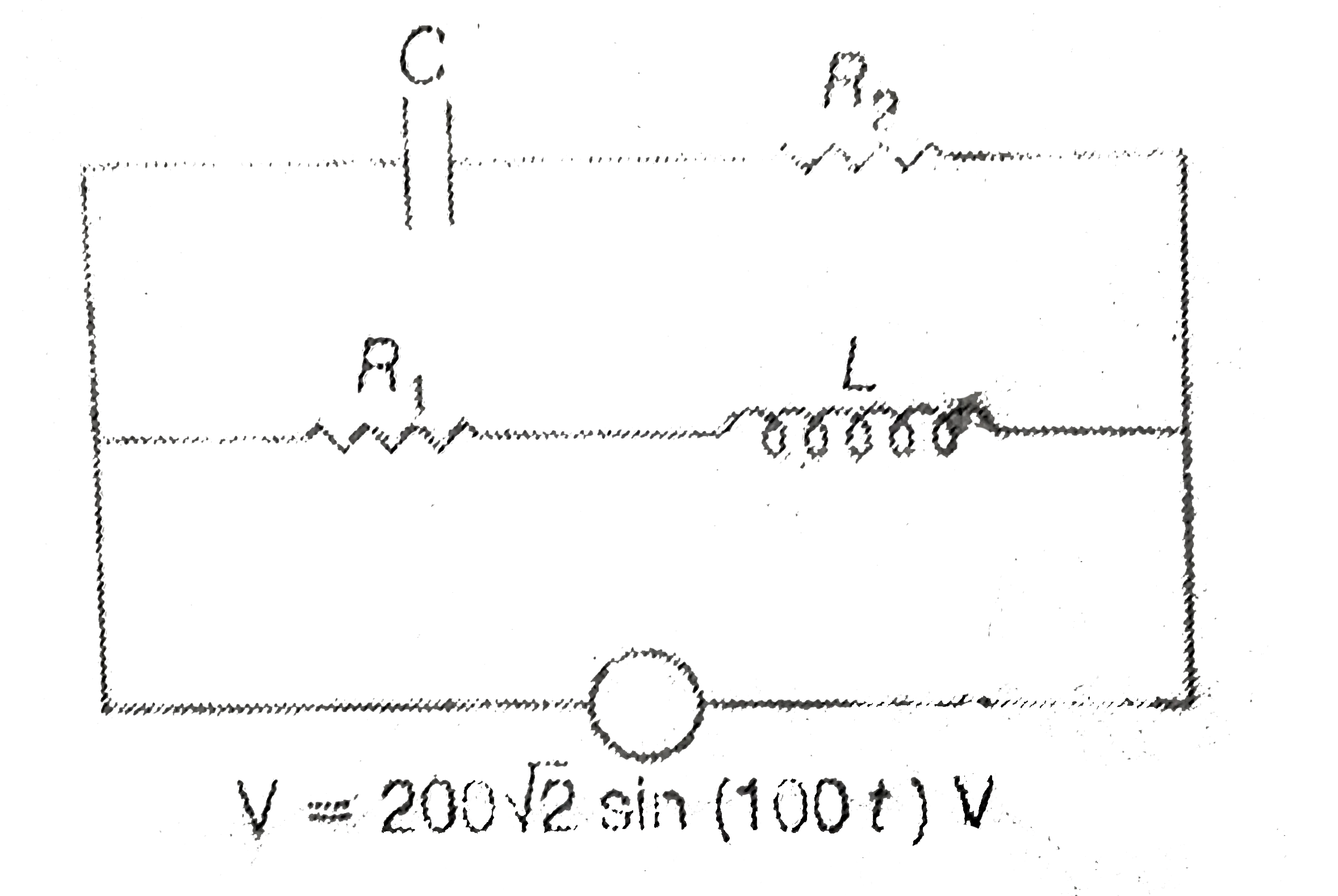
At some instant current in L−R1 circuit is 10A. At the same instant current in C−R2 circuit will be
For R1-L branch
XL=ωL=100×√310=10√3Ω,R1=10Ω
∴tanϕ=XLR1=√3 or ϕ=60∘
Hence current I1 lags voltage by 60∘ For R2−C branch
XC=1ωC=1100×√32×10−3=20√3Ω
∴tanϕ=XCR2=1√3 or ϕ=30∘
Hence current I2 leads voltage by 30∘
∴ The phase difference between I1 and I2 branch is 90∘
The maximum current through R1−L branch is
=V0√R21+ω2L2=200√2√102+(10√3)2=10√2amp.
Hence when current through R1−L branch is 10√2 amp. the current through R2−C branch will be zero.
Topper's Solved these Questions
Similar Questions
In the circuit shown in figure :
R=10Ω,L=√310H,R2=20Ω and C=√32mF. Current in L−R1 circuit is I1 in C−R1 circuit is I2 and the main current is I
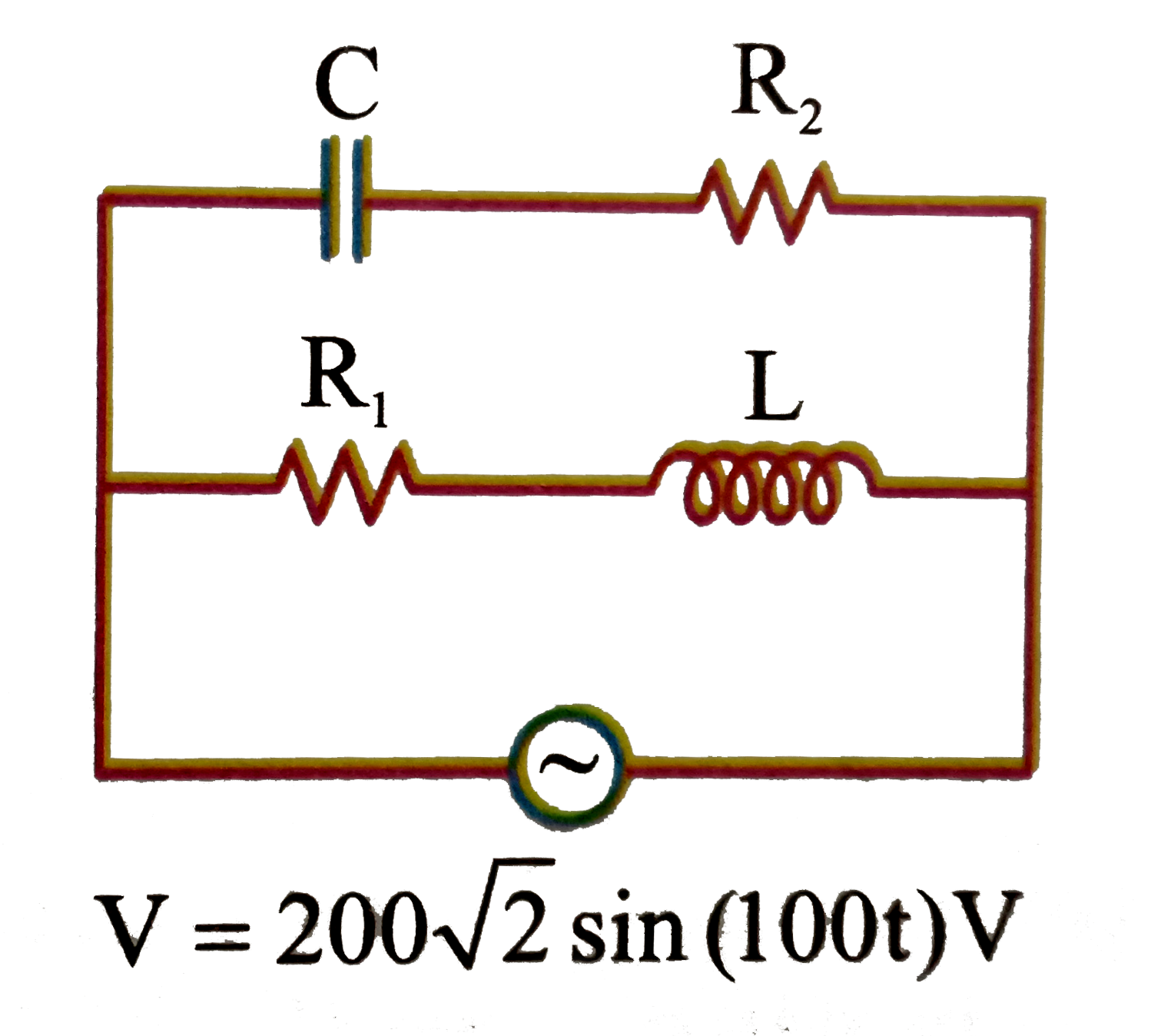
At some instant current in L−R1 circuit is 10A. At the same instant current in C−R2 branch will be
View SolutionIn the circuit shown in figure :
R=10Ω,L=√310H,R2=20Ω and C=√32mF. Current in L−R1 circuit is I1 in C−R1 circuit is I2 and the main current is I
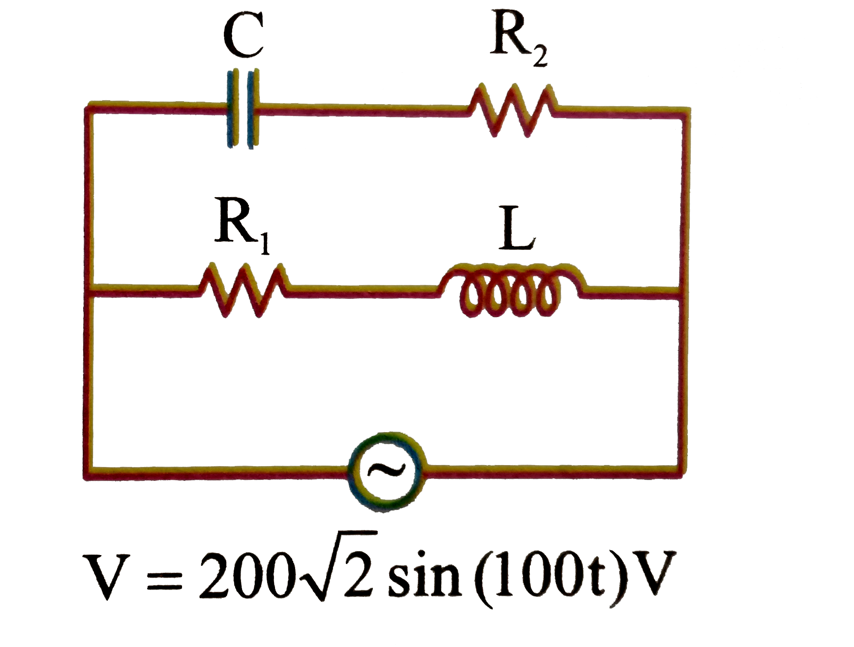
Phase difference between I1 and I2 is
View SolutionIn the circuit shown in figure :
R=10Ω,L=√310H,R2=20Ω and C=√32mF. Current in L−R1 circuit is I1 in C−R1 circuit is I2 and the main current is I

Phase difference between I1 and I2 is
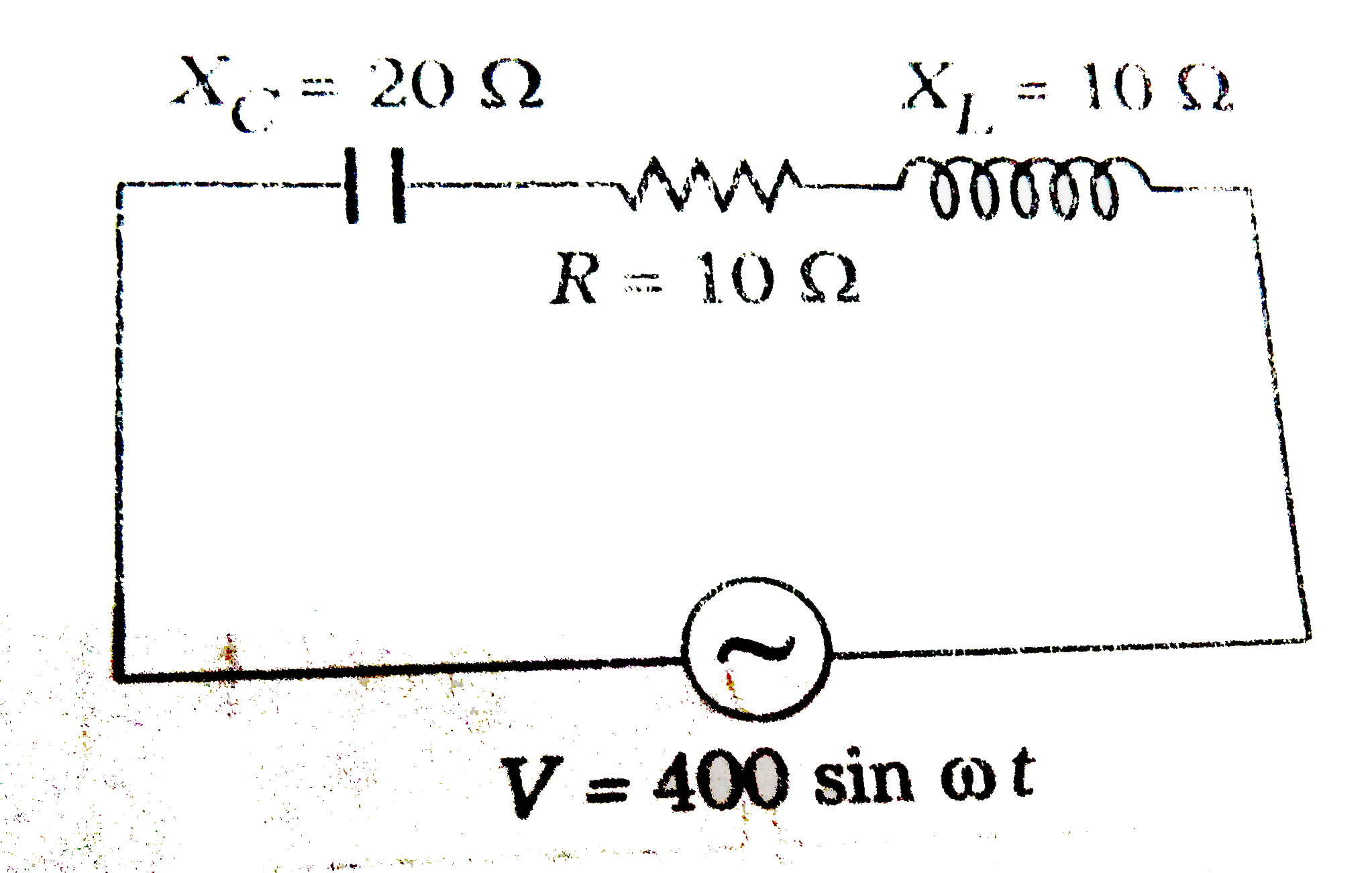
View SolutionIn the L-C-R circuit as shown in figure,
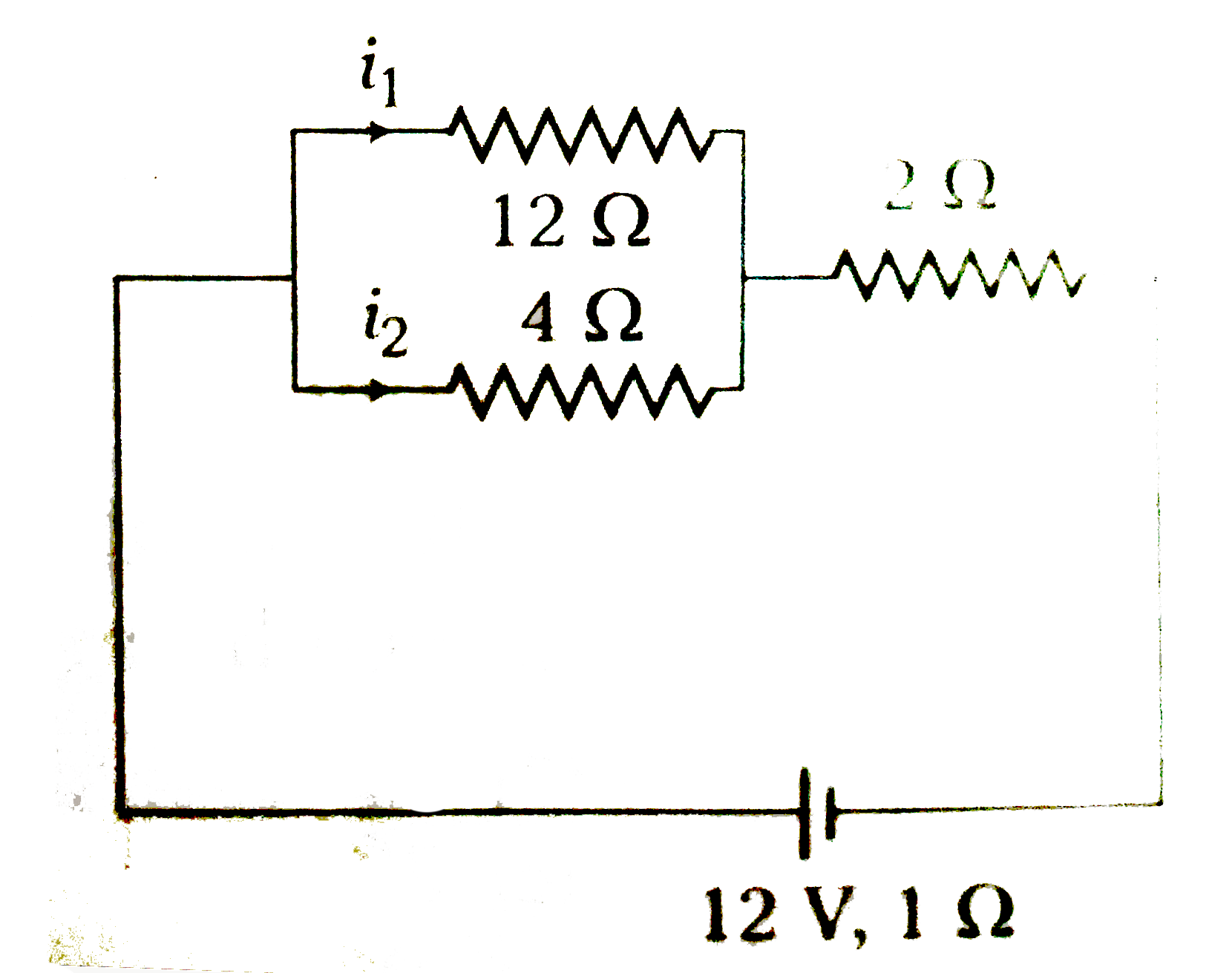
View SolutionIn the circuit shown, the currents i1 and i2 are
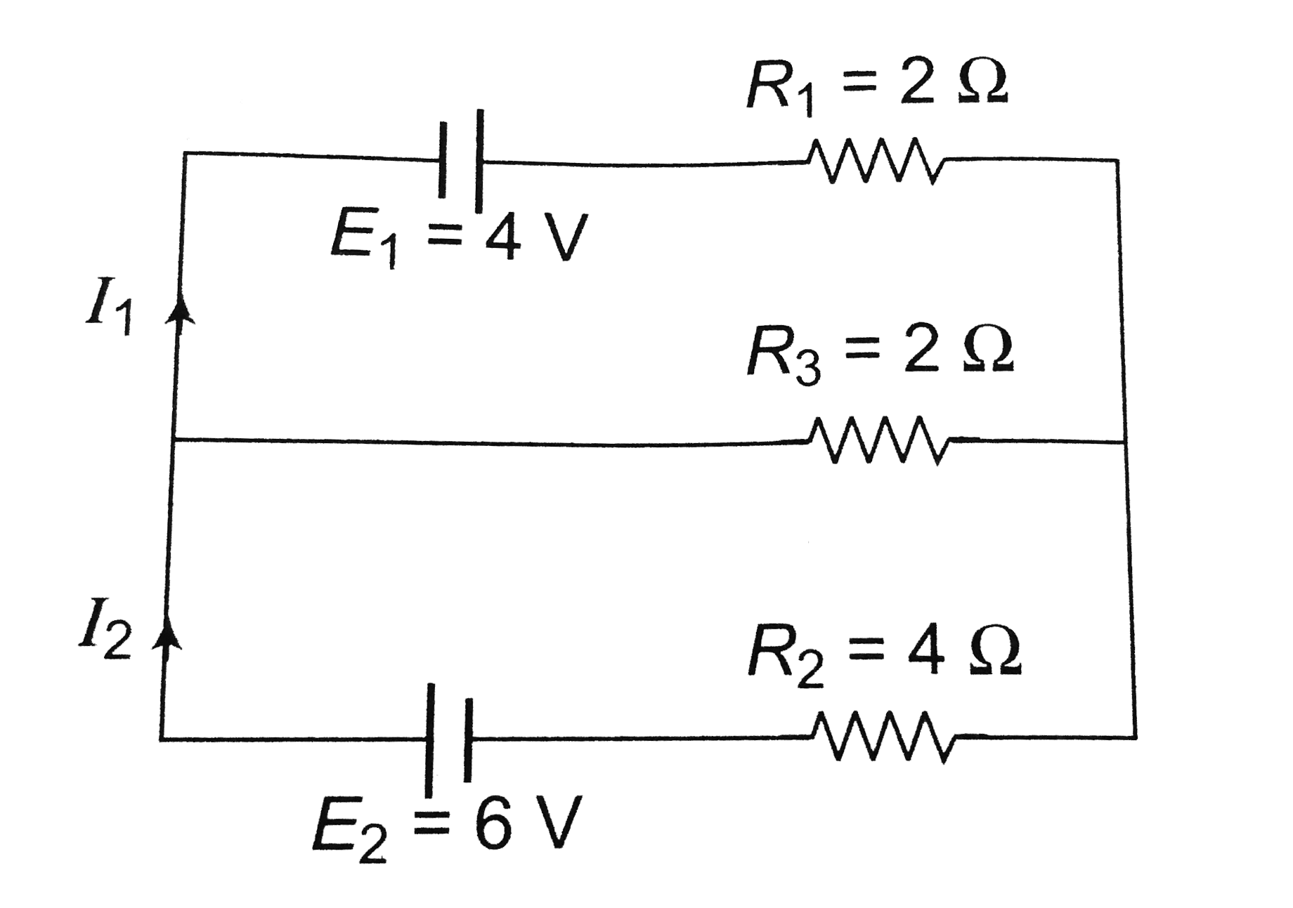
View SolutionIn the circuit shown below E1=4.0V,R1=2Ω,E2=6.0V,R2=4Ω and R3=2Ω. The current I1 is
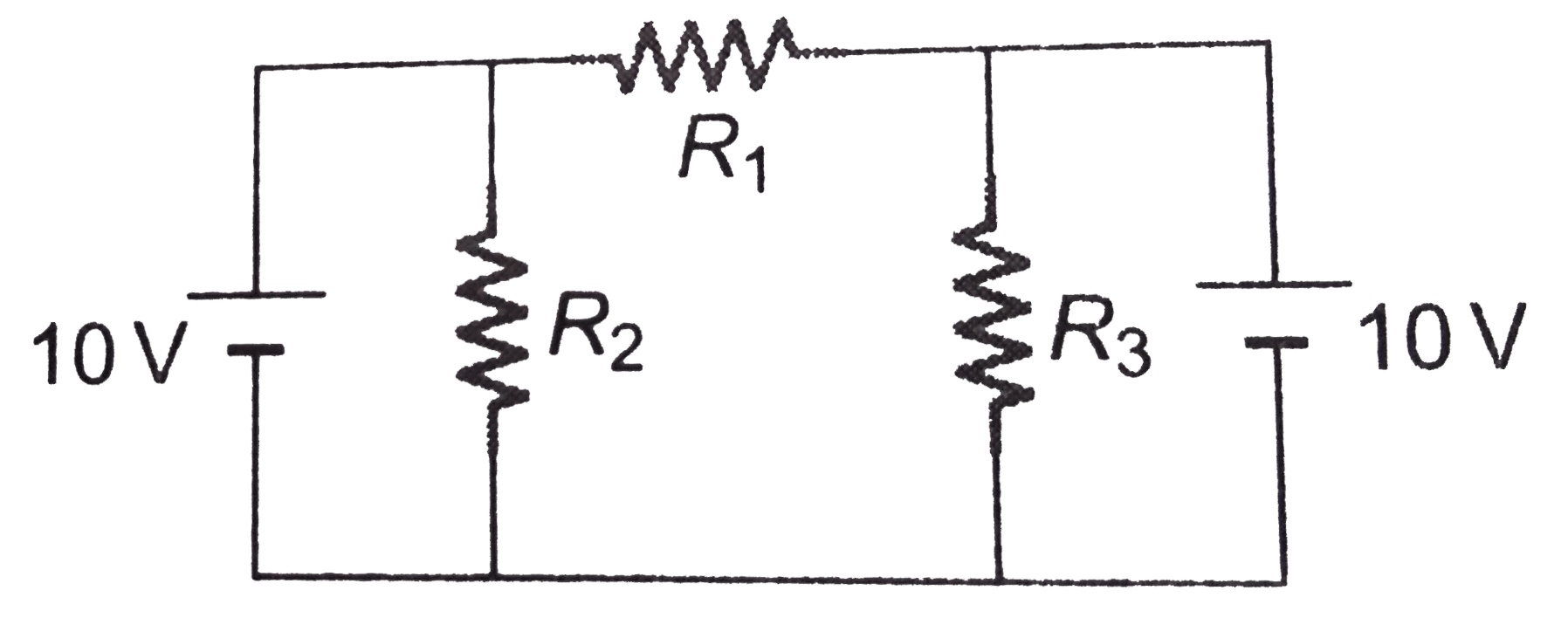
View SolutionIn the curcuit shown in figure R1=R2=R3=10Ω. Find the currents through R1 and R2
View SolutionIn the circuit shown in figure
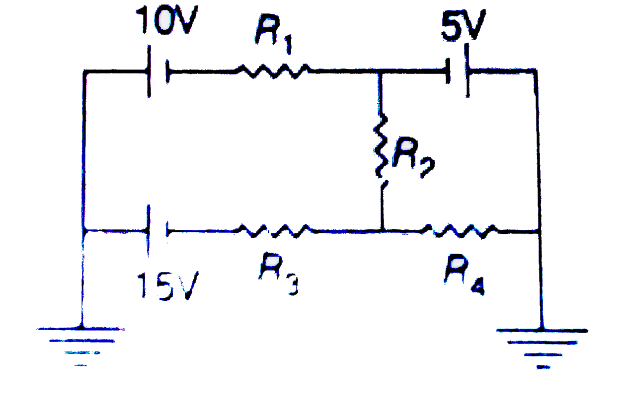
Current through R2 is zero if R4=2Ω and R3=4Ω In this case
View SolutionIn the circuit shown in figure
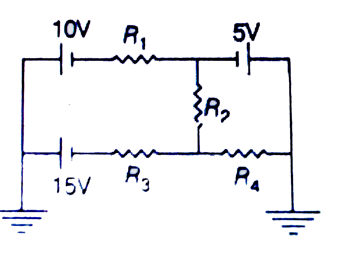
Current thorugh R1 is independent of
View SolutionIn the circuit shown in the figure XL=XC2)=R the peck value current i0 is
View Solution
