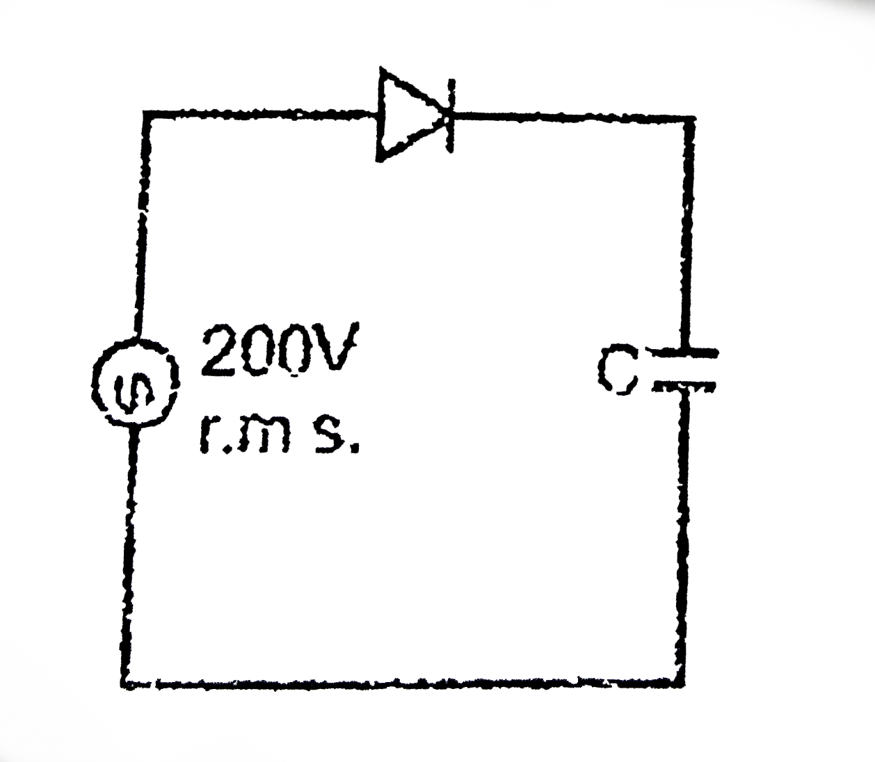
In the figure an A.C of rms voltage 200 volt is appled to the circuit containing diode and the capacitor and it is being rectified. The maximum potential across the capacitor C in volt will be
500
200
283
141
The correct Answer is:C
Step by step video & image solution for In the figure an A.C of rms voltage 200 volt is appled to the circuit containing diode and the capacitor and it is being rectified. The maximum potential across the capacitor C in volt will be by Physics experts to help you in doubts & scoring excellent marks in Class 12 exams.
Updated on:21/07/2023Topper's Solved these Questions
- SEMICONDUCTORSBOOK - RESONANCE ENGLISHCHAPTER - SEMICONDUCTORSEXERCISE - Exercise
100 Videos
- SEMICONDUCTORSBOOK - RESONANCE ENGLISHCHAPTER - SEMICONDUCTORSEXERCISE - Exercise 2
16 Videos
- REVISION DPPBOOK - RESONANCE ENGLISHCHAPTER - REVISION DPPEXERCISE - All Questions
463 Videos
- SIMPLE HARMONIC MOTION BOOK - RESONANCE ENGLISHCHAPTER - SIMPLE HARMONIC MOTION EXERCISE - Advanced Level Problems
13 Videos
Similar Questions
Knowledge Check
When an AC voltage of 220 V is applied to the capacitor C
Athe maximum voltage between plates is 220 V.Bthe current is in phase with the applied voltage.Cthe charge on the plate is not in phase with the applied voltage.Dpower delivered to the capacitor per cycle is zero.A capacitor or capacitance C1 is charge to a potential V and then connected in parallel to an uncharged capacitor of capacitance C2. The fianl potential difference across each capacitor will be
AC1VC1+C2BC2VC1+C2C1+C2C1D1−C2C1
Show that the current leads the voltage in phase by π/2 in an a.c. circuit containing an ideal capacitor.
View SolutionA 20volts AC is applied to a circuit consisting of a resistance and a coil with negligible resistance. If the voltage across the resistance is 12V, the voltage across the coil is
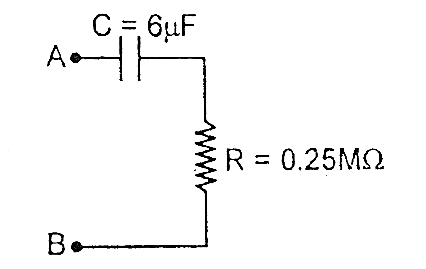
View SolutionA time varying voltage is applied across A & B such that voltage across capacitor is given by VC=2sin2t. What is maximum potential difference across the reistance?

View SolutionFor the circuit shown in figure, determine the voltage across 4Ω resistors in volt ?

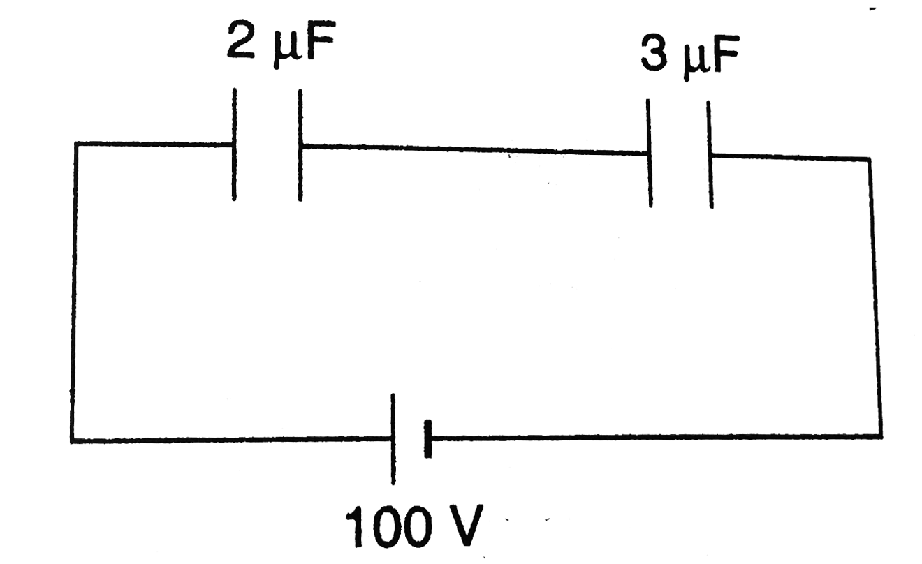
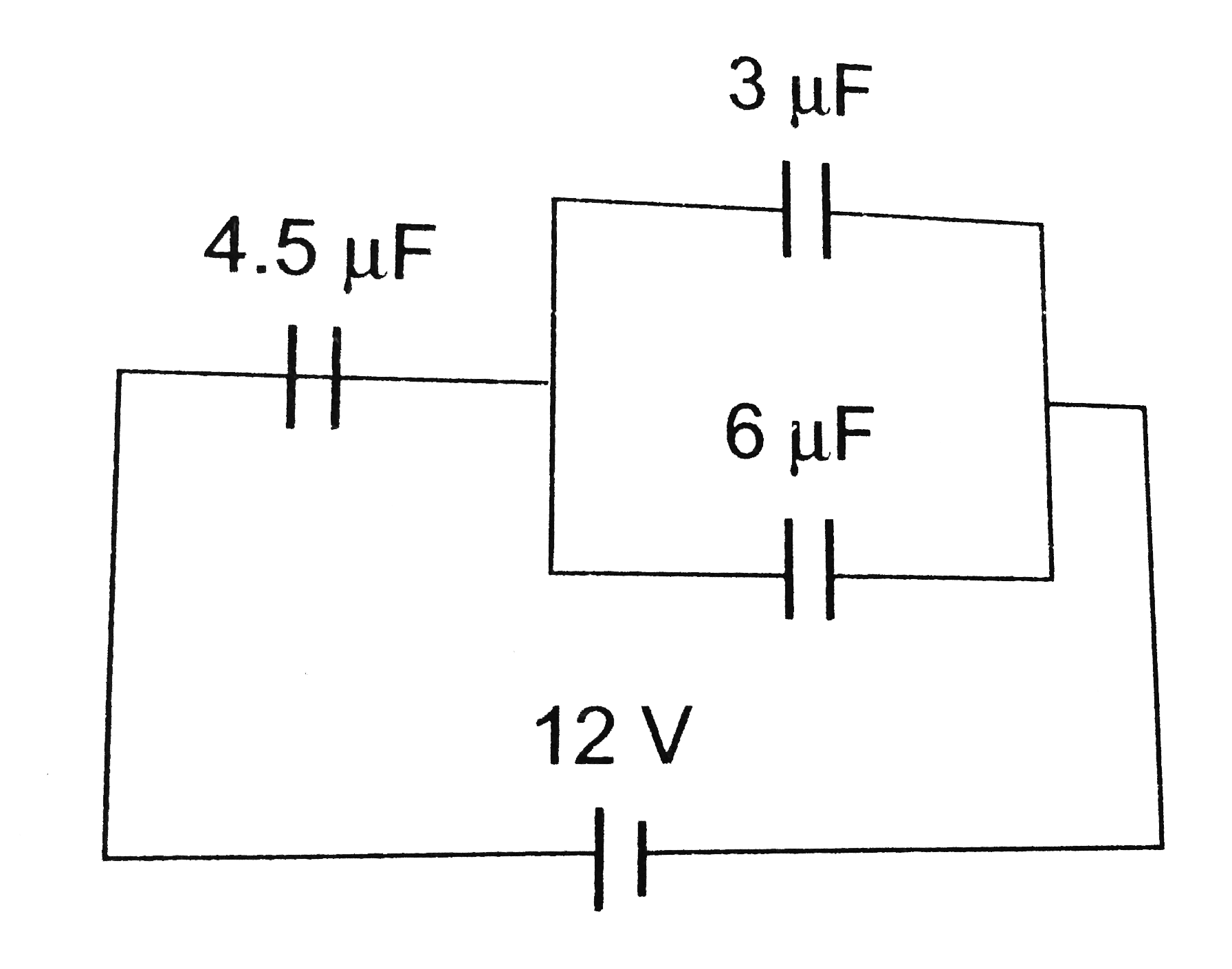
View SolutionIn the circuit shown in figure find

a. the equivalent capacitance
b. the charge stored in each capacitor and
c. the potential difference across each capacitor.
View SolutionFour capacitors are arranged as shown. All are initially uncharged. A 30 V battery is palced across terminal PQ to charge the capacitors and is then removed. The voltage across the terminals RS is then (in volt)

View Solution

