In the circuit shown in fig. the cell has emf 10V and internal resistance 1Ω
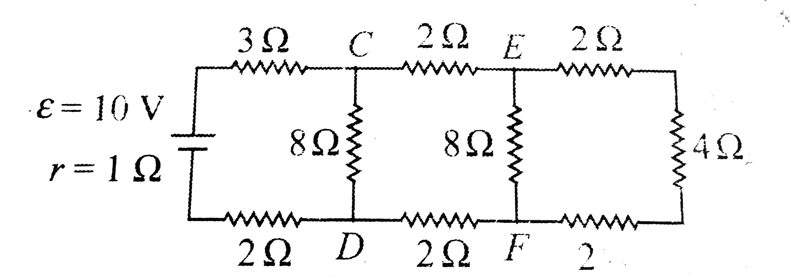
The current though the 3Ωresistor is 1 A.
The current though the 3Ω resistor is 0.5 A
The current through the 4Ωresistor is 0.5 A
The current through the 4Ω resistor is 0.25 A
The correct Answer is:A, D
Step by step video & image solution for In the circuit shown in fig. the cell has emf 10V and internal resistance 1 Omega by Physics experts to help you in doubts & scoring excellent marks in Class 12 exams.
Updated on:21/07/2023Topper's Solved these Questions
- CURRENT ELECTRICITYBOOK - RESONANCE ENGLISHCHAPTER - CURRENT ELECTRICITYEXERCISE - Exercise-2 (Part-4)
12 Videos
- CURRENT ELECTRICITYBOOK - RESONANCE ENGLISHCHAPTER - CURRENT ELECTRICITYEXERCISE - Exrcies-3(PART-1)
22 Videos
- CURRENT ELECTRICITYBOOK - RESONANCE ENGLISHCHAPTER - CURRENT ELECTRICITYEXERCISE - Exercise-2 (Part-2)
16 Videos
- COMMUNICATION SYSTEMSBOOK - RESONANCE ENGLISHCHAPTER - COMMUNICATION SYSTEMSEXERCISE - Exercise 3
13 Videos
- DAILY PRACTICE PROBLEMBOOK - RESONANCE ENGLISHCHAPTER - DAILY PRACTICE PROBLEMEXERCISE - DPP.No.71
1 Videos
Similar Questions
In the situation shown each cell has e.m.f. 4V and internal resistance 1Ω. The maximum power that can be delivered to the variable load resistance R is

View SolutionIn the circuit shown below, E is a battery of emf 6 V and internal resistance 1Ω. Find the reading of the ammeter A. if it has negligible resistance :

View Solution
Knowledge Check
Two cells e1ande2 connected in opposition to each other as shown in figure. The cell of emf 9 V and internal resistance 3Ω the cell is of emf 7V and internal resistance 7Ω. The potential difference between the points A and B is
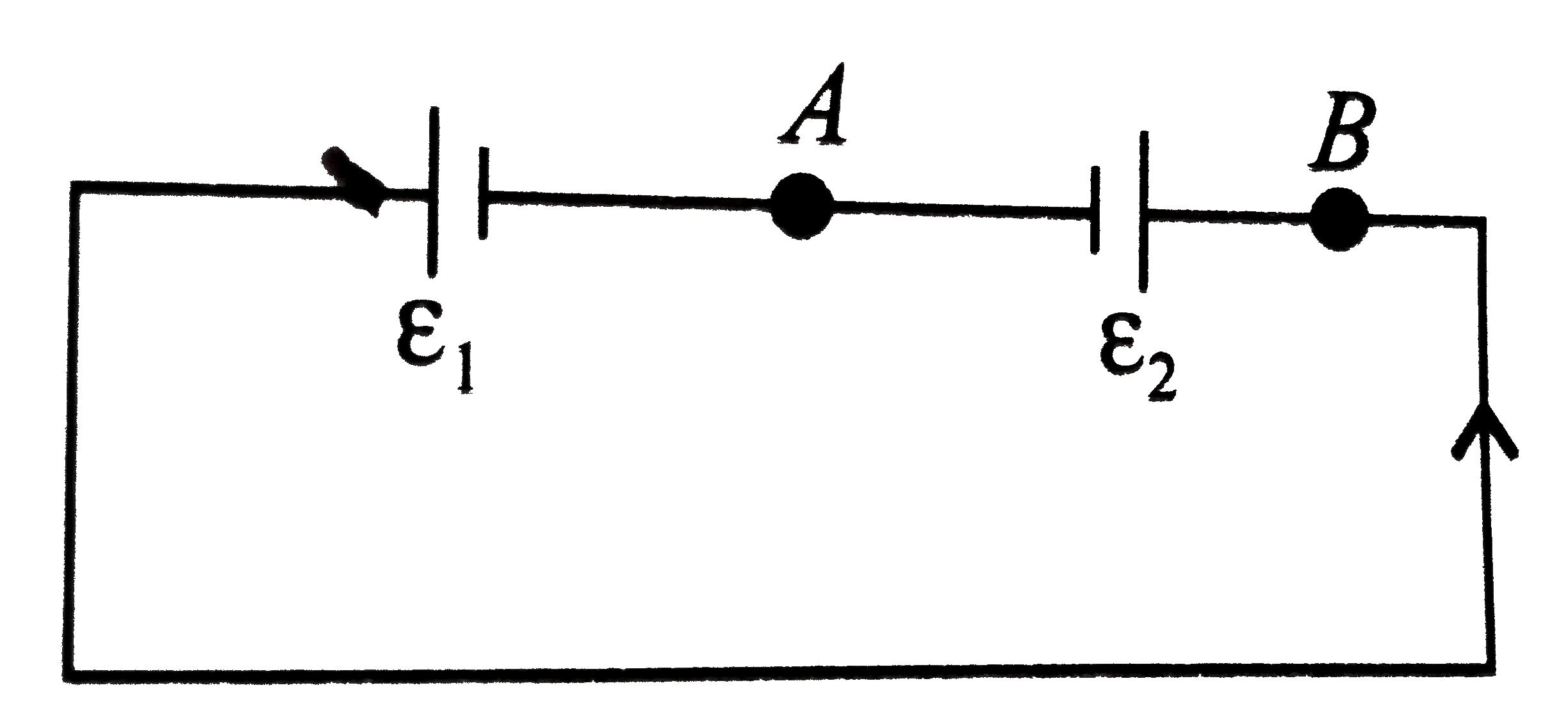 A8.4VB5.6VC7.8VD6.6V
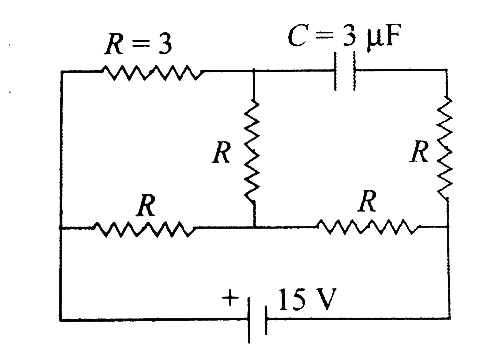
In the circuit shown in fig. the cell is ideal with emf 15V. Each resistance is of 3Ω. The potential difference across the capacitoro in steady state is
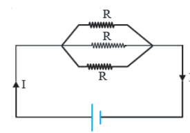
View SolutionThree equal resistances, each of RΩ are connected as shown in figure. A battery of emf 2 V and internal resistance 0.1Ω is connected across the circuit. Calculate the value of R for which the heat generated in the circuit is maximum?
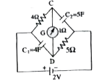
View SolutionIn the circuit shown in Fig., the cell is ideal with e.m.f = 2V. The resistance of the coil of the galvanometer G is 1Ω. Then
View SolutionIn a potentiometer circuit, the emf of driver cell is 2V and internal resistance is 0.5Ω. The potentiometer wire is 1m long . It is found that a cell of emf 1V and internal resistance 0.5Ω is balanced against 60 cm length of the wire. Calculate the resistance of potentiometer wire.
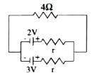
View SolutionTwo cell with unequal emfs of 2V and 3V are connected as shown in the figure. If each cell has an internal resistance r = 0.45Ω and external resistance is of 4Ω. Then, Potential drop across resistor 4Ω is
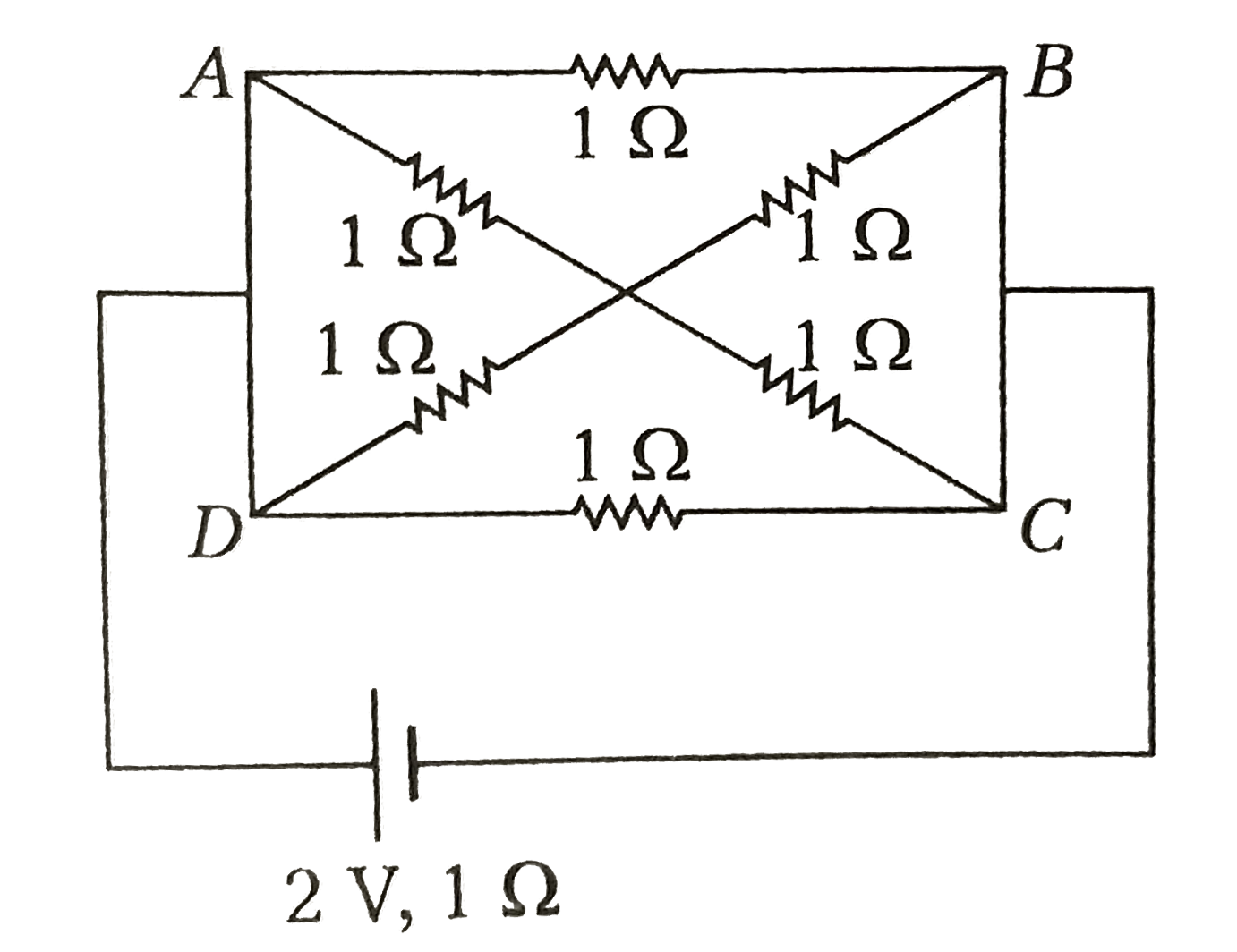
View SolutionFind the current drawn from a cell of emf 2 V and internal resistance 2Ω connected to the network given below.
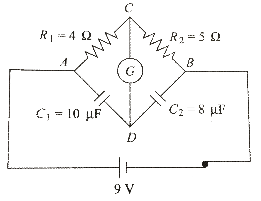
View SolutionIn the circuit shows in Fig. 6.63, the cell is ideal with emf 9V. If the resistance of the coil of galvanometer is 1Ω, then
View Solution
