Two capacitors with capacities C1 and C2 ,are charged to potentials V1 and V2 respectively.When they are connected in parallel,the ratio of their respective charges is ....?
To solve the problem of finding the ratio of the charges on two capacitors when they are connected in parallel, we can follow these steps:
1. Understand the Capacitor Basics:
- The charge Q on a capacitor is given by the formula:
Q=C⋅V
where C is the capacitance and V is the potential difference across the capacitor.
2. Identify the Capacitors and Their Values:
- We have two capacitors with capacitances C1 and C2.
- They are charged to potentials V1 and V2 respectively.
3. Connecting Capacitors in Parallel:
- When capacitors are connected in parallel, they share the same potential difference V. This means that the potential difference across both capacitors will be the same when connected together.
4. Calculate the Charges on Each Capacitor:
- The charge on the first capacitor when connected in parallel is:
Q1=C1⋅V
- The charge on the second capacitor is:
Q2=C2⋅V
5. Finding the Ratio of Charges:
- To find the ratio of the charges Q1 and Q2, we can write:
Q1Q2=C1⋅VC2⋅V
- The V cancels out, leading to:
Q1Q2=C1C2
6. Final Result:
- Therefore, the ratio of the charges on the two capacitors when connected in parallel is:
Q1Q2=C1C2
- The charge Q on a capacitor is given by the formula:
Q=C⋅V
where C is the capacitance and V is the potential difference across the capacitor.
- We have two capacitors with capacitances C1 and C2.
- They are charged to potentials V1 and V2 respectively.
- When capacitors are connected in parallel, they share the same potential difference V. This means that the potential difference across both capacitors will be the same when connected together.
- The charge on the first capacitor when connected in parallel is:
Q1=C1⋅V
- The charge on the second capacitor is:
Q2=C2⋅V
- To find the ratio of the charges Q1 and Q2, we can write:
Q1Q2=C1⋅VC2⋅V
- The V cancels out, leading to:
Q1Q2=C1C2
- Therefore, the ratio of the charges on the two capacitors when connected in parallel is:
Q1Q2=C1C2
Topper's Solved these Questions
- BOOK - VMC MODULES ENGLISHCHAPTER - CAPACITORSEXERCISE - LEVEL 0 (LONG ANSWER TYPE)3videos
CAPACITORS
- BOOK - VMC MODULES ENGLISHCHAPTER - CAPACITORSEXERCISE - LEVEL 1 (MCQs)60videos
CAPACITORS
- BOOK - VMC MODULES ENGLISHCHAPTER - CAPACITORSEXERCISE - JEE Advance ( Archive ) LEVEL 481videos
CAPACITORS
- BOOK - VMC MODULES ENGLISHCHAPTER - BASIC MATHEMATICS & VECTORSEXERCISE - Impeccable50videos
BASIC MATHEMATICS & VECTORS
- BOOK - VMC MODULES ENGLISHCHAPTER - CURRENT ELECTRICITYEXERCISE - IN-CHAPTER EXERCISE-F10videos
CURRENT ELECTRICITY
Similar Questions
Two capacitors having capacitances C1 and C2 are charged with 120 V and 200 V batteries respectively. When they are connected in parallel now, it is found that the potential on each one of them is zero. Then,
View SolutionTwo capacitors having capacitances C1 and C2 are charged with 120 V and 200 V batteries respectively. When they are connected in parallel now, it is found that the potential on each one of them is zero. Then,
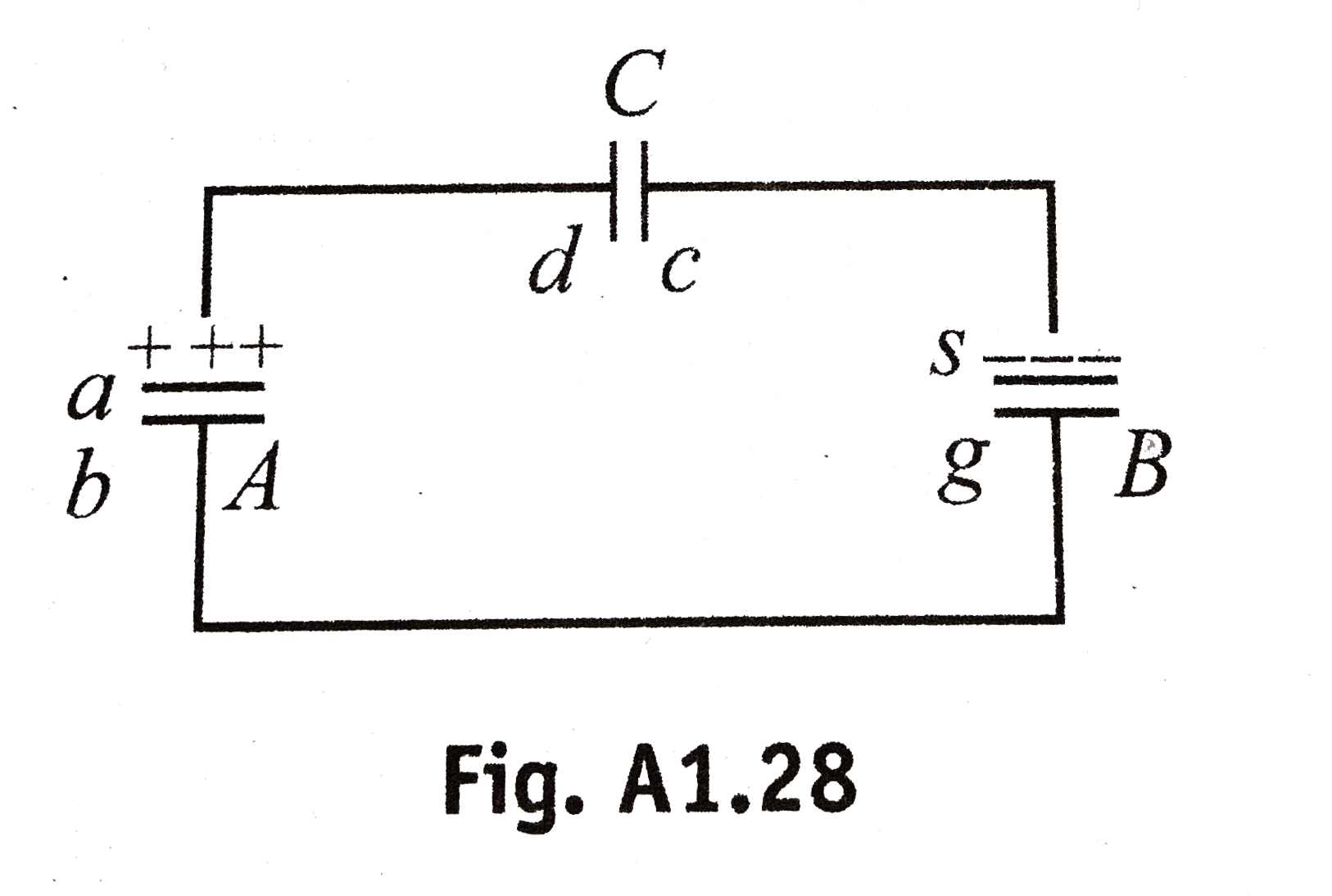
View SolutionTwo capacitors A and B with capacities C1andC2 are charged to potential difference of V1andV2 respectively. The plates of the capacitors are connected as shown in the figure with one wire free from each capacitor. The upper plate of A is positive and that of B is negative. An uncharged capacitor of capacitance C3 and lead wires falls on the free ends to complete circuit, then
 View Solution
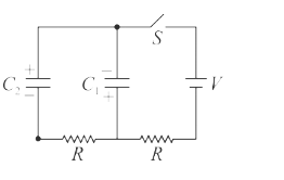
Two capacitors, C1andC2, charged to a potential V2 and V respectively with polarities as shown, are connected in a circuit with an ideal battery of EMF V. The capacitances are C1=2C and aC_(2)=C.Att=0, the switch S is closed. A long time after S is closed,
 View Solution
Two capacitors of capacitance C and 3C are charged to potential difference V0 and 2V0, respectively, and connected to an inductor of inductance L as shows in Fig. Initially, the current in the inductor is zero. Now, switch S is closed.
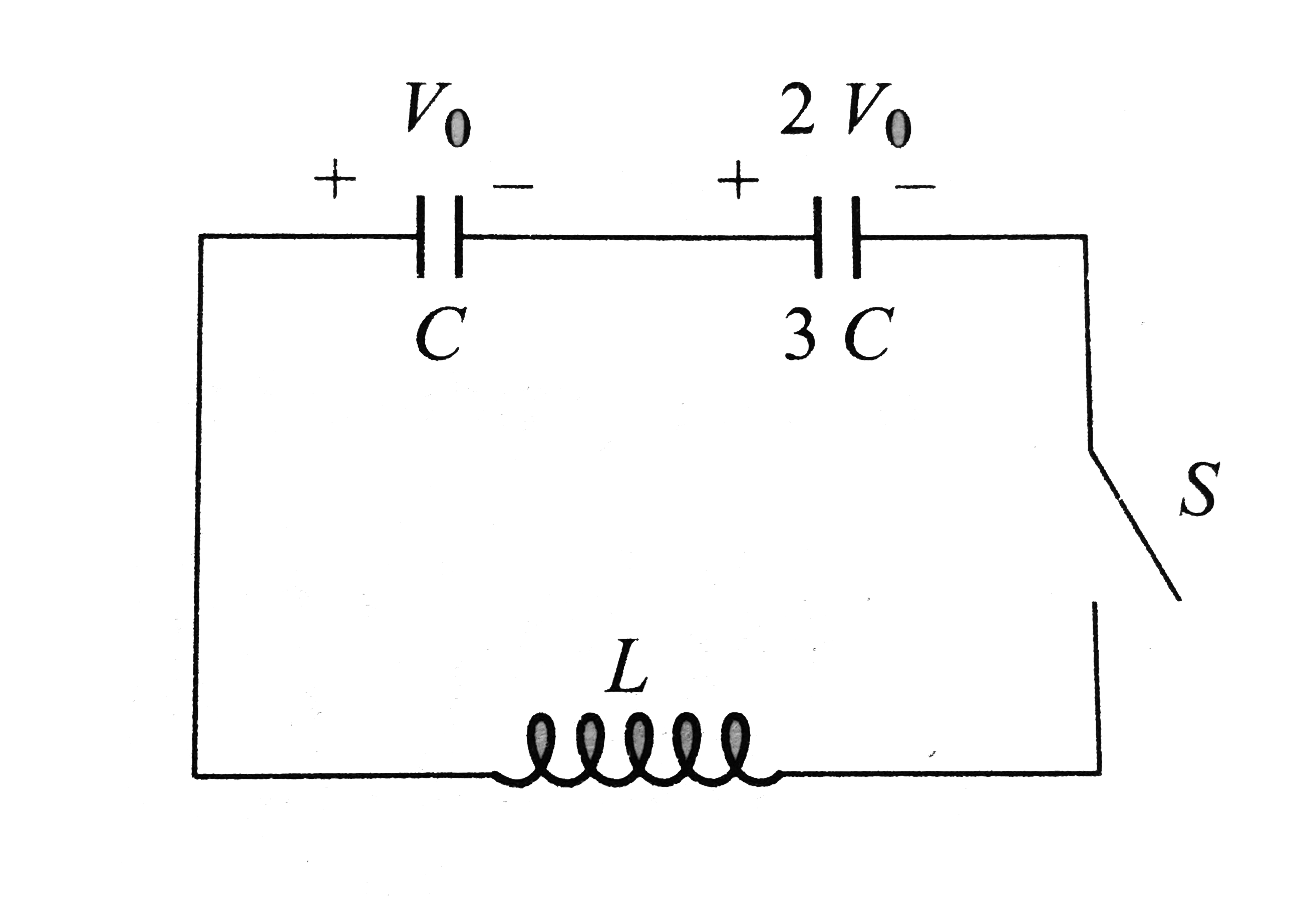
Potential difference across capacitor of capacitance C when the current in the circuit is maximum isView SolutionTwo capacitors of capacitance C and 3C are charged to potential difference V0 and 2V0, respectively, and connected to an inductor of inductance L as shows in Fig. Initially, the current in the inductor is zero. Now, switch S is closed.
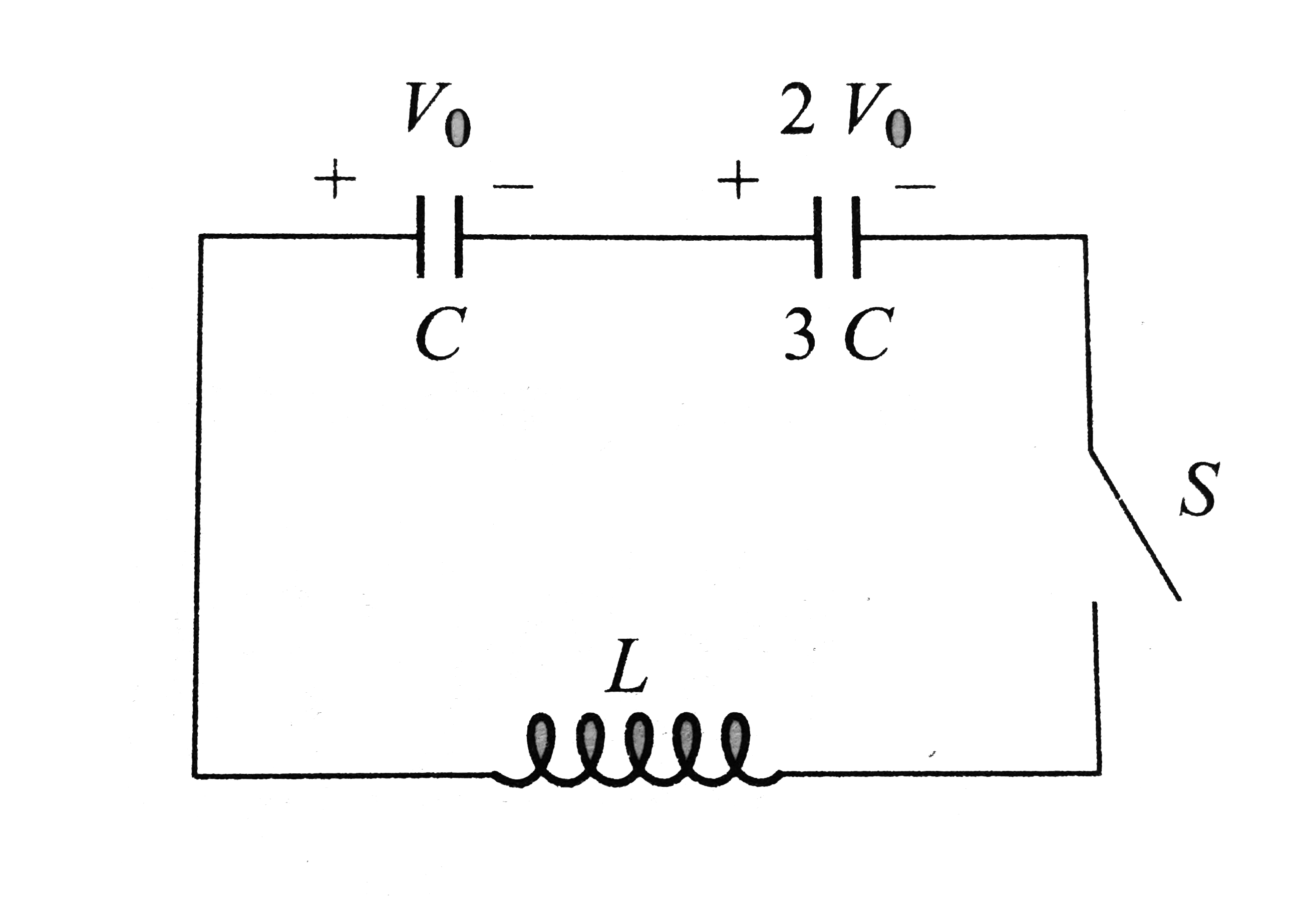
Potential difference across capacitor of capacitance 3C when the current in the circuit is maximum isView SolutionTwo capacitors of capacitance C and 3C are charged to potential difference V0 and 2V0, respectively, and connected to an inductor of inductance L as shows in Fig. Initially, the current in the inductor is zero. Now, switch S is closed.
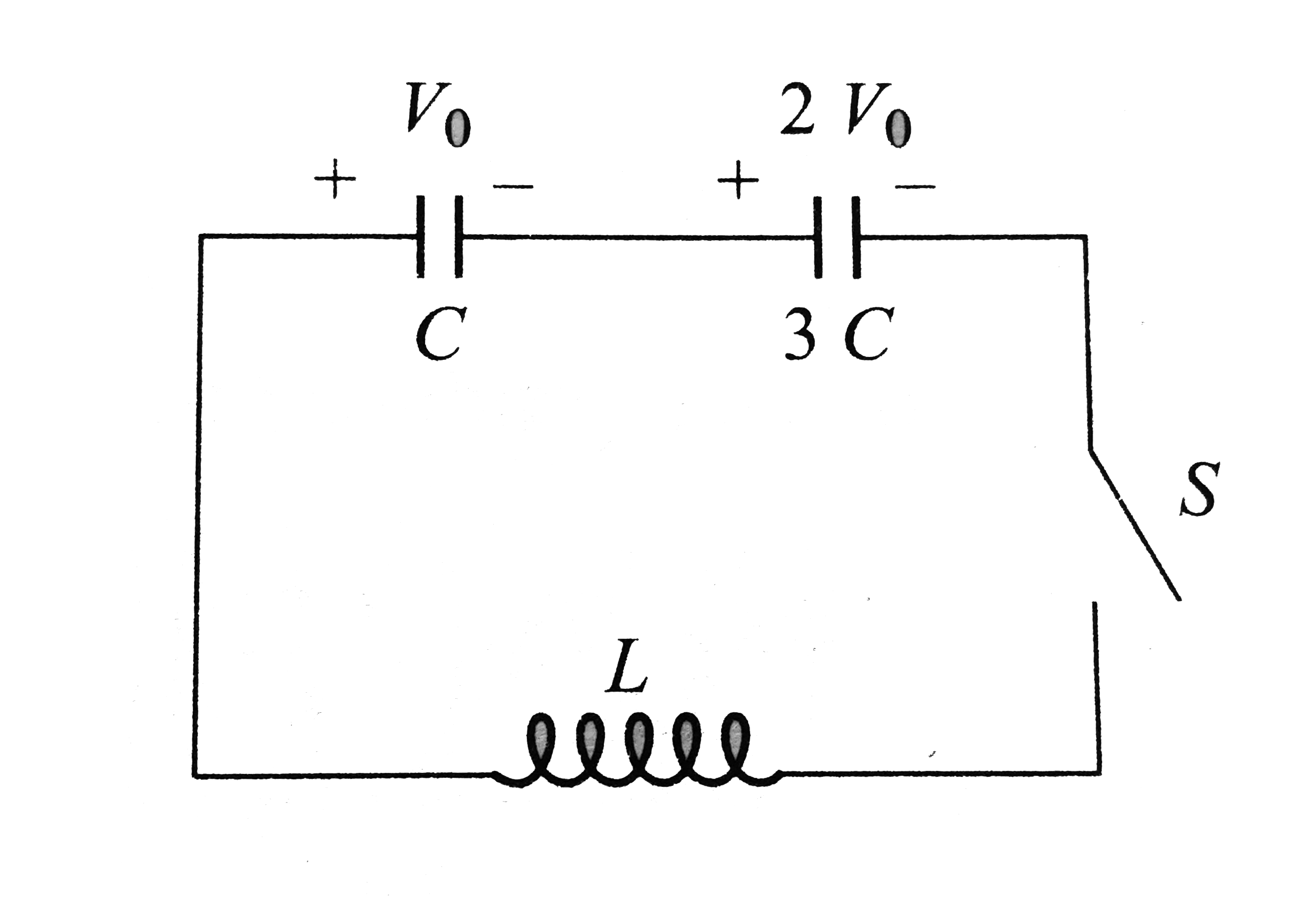
The maximum current in the inductor isView SolutionThe capacities of two conductors are C1 and C2 and their respectively potentials are V1 and V2. If they are connected by a thin wire, then the loss of energy will be given by
View SolutionTwo capacitors of capacitance 2μF and 3μF respectively are charged to potential difference 20 V and 40 V respectively. Now the capacitors are connected in series with a resistance such that the positively charged plate of one capacitor is connected to the positively charged plate of the other. The initial current through the resistance is I0. The potential difference across the 2μF capacitor at the instant the current has reduced to I02 is_______ V.
View SolutionTwo identical capacitors, have the same capacitance C. One of them is charged to potential V1 and the other V2. The negative ends of the capacitors are connected together. When the poistive ends are also connected, the decrease in energy of the combined system is
View Solution

