Which of the following statements is correct about the circuit shown in Fig. where 1Ωand0.5Ω are the internal resistances of the 6 V and 12 V batteries respectively?
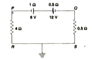
The potential at point P is 6 V.
The potential at point Q is +0.5 V
If a volmeter is connected across the 6 battery, it will read 7 V
If a volmeter is connected across the 6 battery, it will read 5 V
The correct Answer is:C
Total resistance =4+1+0.5+0.5=6Ω. Net voltage in the circuit is 6 V. Current I=66=IA in the anticlockwise direction
VPR=1×4=4V
Since R is connected to earth, VR=0. Hence VP=4V.
VSQ=0.5×1=0.5V
S is at a higher potential than Q
∴VQ=−0.5V
Current is being forced into the 6 V battery in the opposite direction.
Hence V6=E+Ir=6+1×1=7V
Similar Questions
Knowledge Check
In the circuit shown in fig. the cell has emf 10V and internal resistance 1Ω
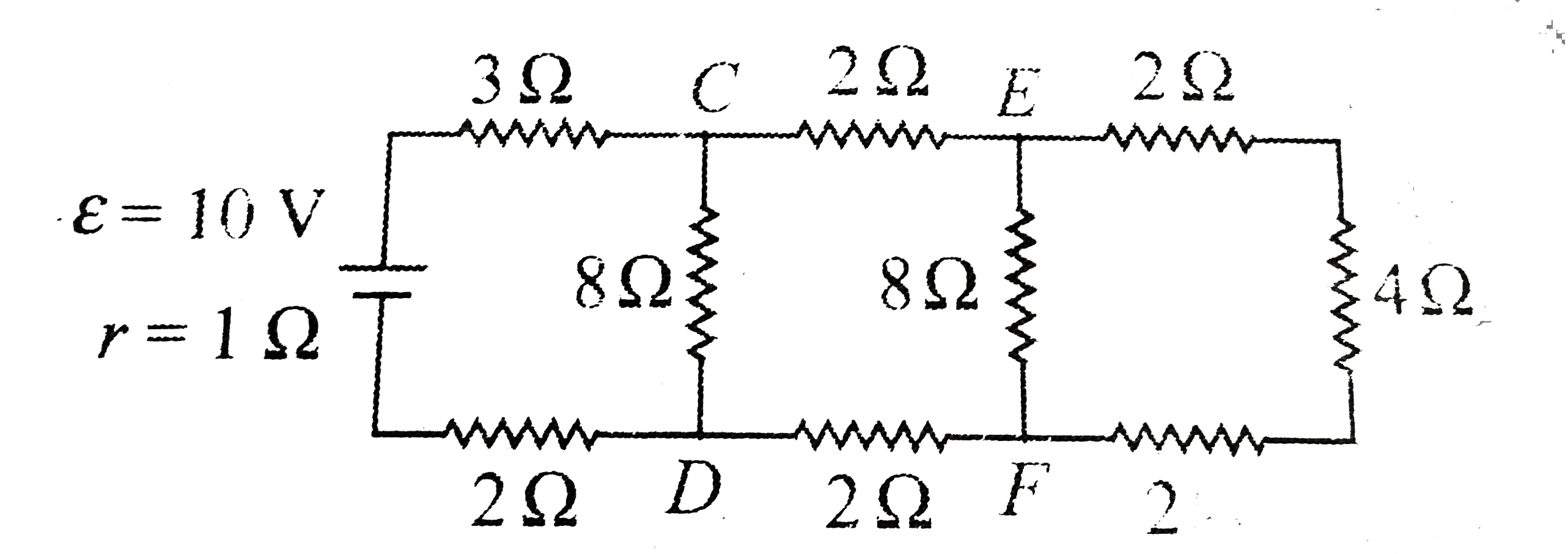 AThe current through the 3Ω resistor is 1A.BThe currents through the 3Ω resistor is 0.5 A.CThe currents through the 4Ω resistor is 0.5 ADThe current through the 4Ω resistor is 0.25 A.
Two batteries with emf 12V and 13V are connected in parallel across a load resistor of 10Ω. The internal resistances of the two batteries are 1Ωand2Ω respectively. The voltage across the load lies between
A11.4V and 11.5VB11.7 V and 11.8VC11.6V and 11.7VD11.5 V and 11.6V
in the circuit shown in the figure, each battery is of 5 V and has an internal resistance of 0.2 Omega What is the reading of the ideal voltmeter V
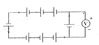
View Solutionin the circuit shown in the figure, each battery is of 5 V and has an internal resistance of 0.2 Omega What is the reading of the ideal voltmeter V

View SolutionTwo batteries with emf 12 V and 13V are connected in parallel across a load resistor of 10Ω . The internal resistances of the two batteries are 1Ωand2Ω respectively . The voltage across the load lies between
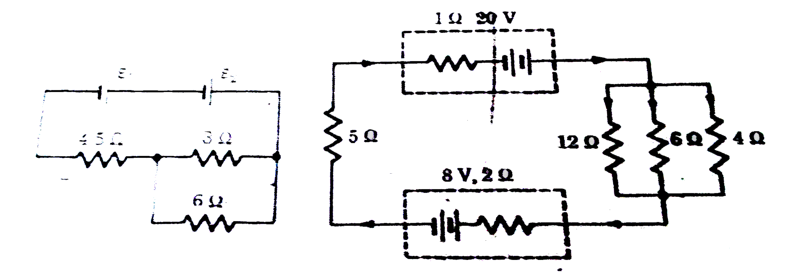
View SolutionIn the circuit shown in Fig. 4.68, the cells ε1 and ε2 have emf's of 4 V and 8 V and internal resistances of 0.5Ω and 1Ω respectively. Calculate the current in each resistance.
View SolutionIn the circuit shown E,F,G and H are cells of emf 2V,1V,3V and 1V respectively and their internal resistance are 2Ω,1Ω,3Ω and 1Ω respectively.
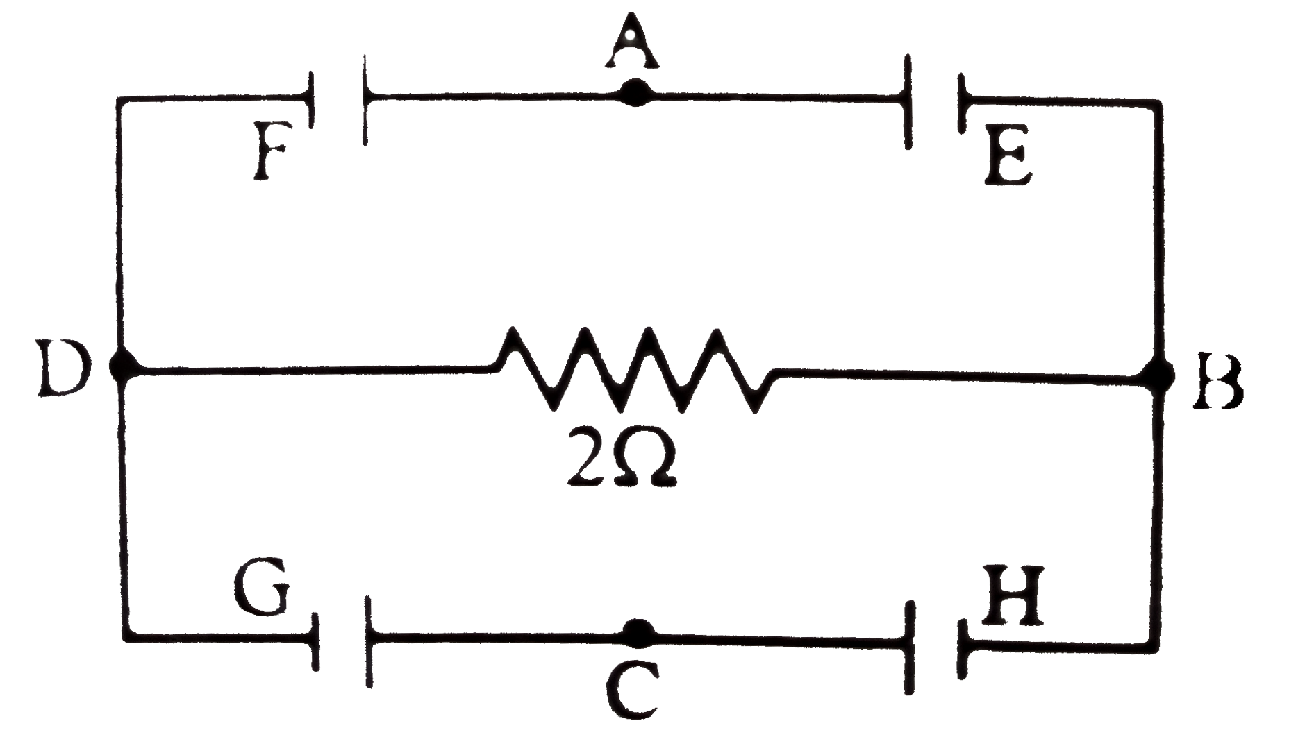
View SolutionIn the circuit shown E,F,G and H are cells of emf 2V,1V,3V and 1V respectively and their internal resistance are 2Ω,1Ω,3Ω and 1Ω respectively.

View Solution

