A blackbox (BB) which may contain a combination of electrical circuit elements (resistor, capacitor or inductor) is connected with other external circuit elements as shown below in the figure (a). After the switch (S) is closed at time t = 0, the current (I) as a function of time (t) is shown in the figure (b).
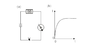
From this we can infer that the blackbox contains
A resistor and a capacitor in series
A resistor and a capacitor in parallel
A resistor and an inductor in series
A resistor and an inductor in parallel
The correct Answer is:C
I-t graph is for L-R series circuit
Topper's Solved these Questions
- QUESTION PAPER 2013BOOK - KVPY PREVIOUS YEARCHAPTER - QUESTION PAPER 2013EXERCISE - PART-II ( PHYSICS)
10 Videos
- QUESTION PAPER 2013BOOK - KVPY PREVIOUS YEARCHAPTER - QUESTION PAPER 2013EXERCISE - PART-II (PHYSICS)
5 Videos
- MOCK TEST 9BOOK - KVPY PREVIOUS YEARCHAPTER - MOCK TEST 9EXERCISE - EXERCISE
19 Videos
- QUESTION PAPER 2020BOOK - KVPY PREVIOUS YEARCHAPTER - QUESTION PAPER 2020EXERCISE - PART-I : PHYSICS
50 Videos
Similar Questions
Knowledge Check
In the circuit shown in the figure, switch S is closed at time t=0. Select the correct statements.
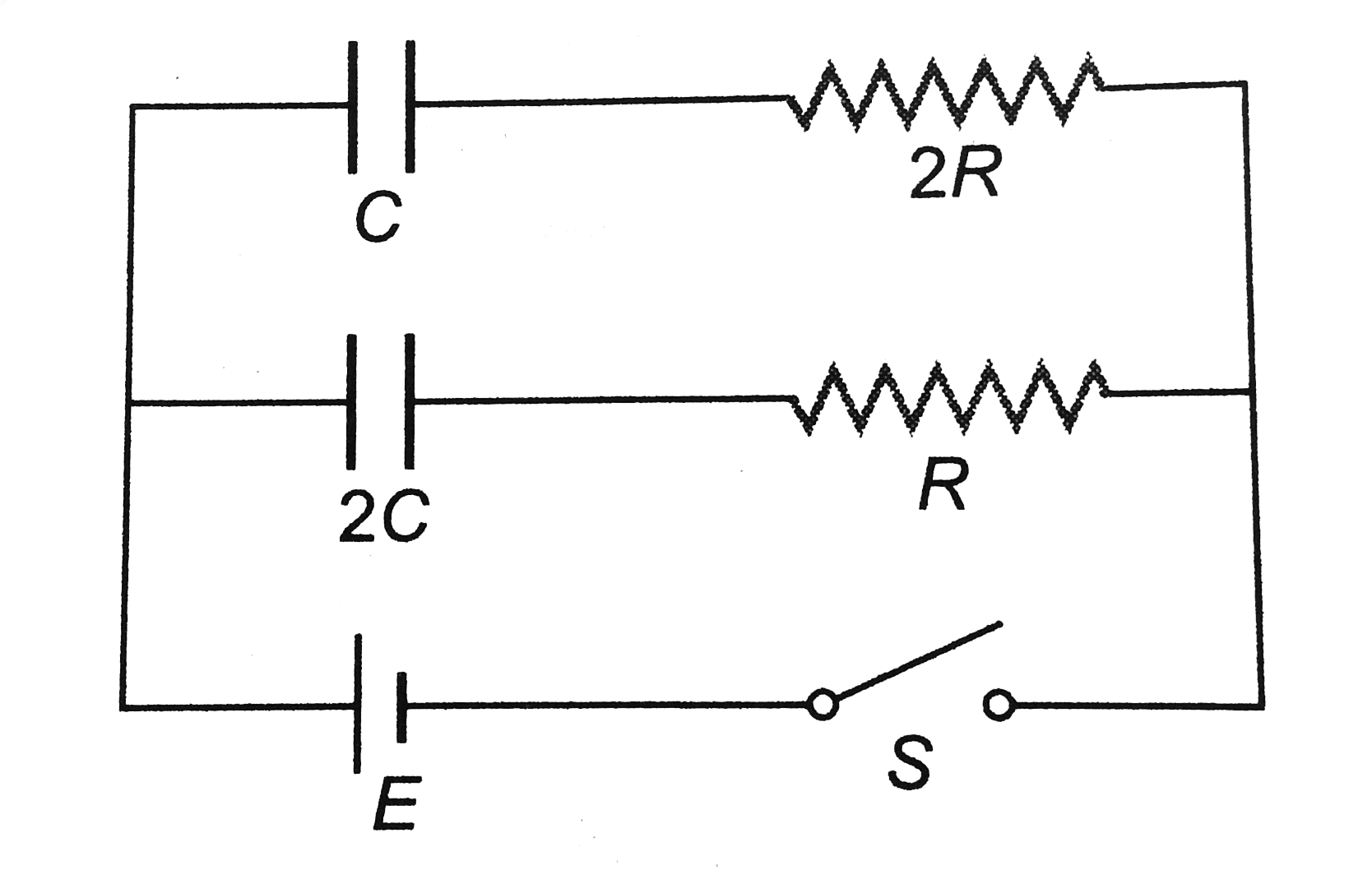 ARate of increase of charge is same in both the capacitorsBRatio of charge stored in capacitors C and 2C at any time t would be 1:2CTime constants of both the capacitors are equalDSteady state chares on capacitors C and 2C are in the ratio of 1:2
In the circuit shown in figure switch S is closed at time t=0
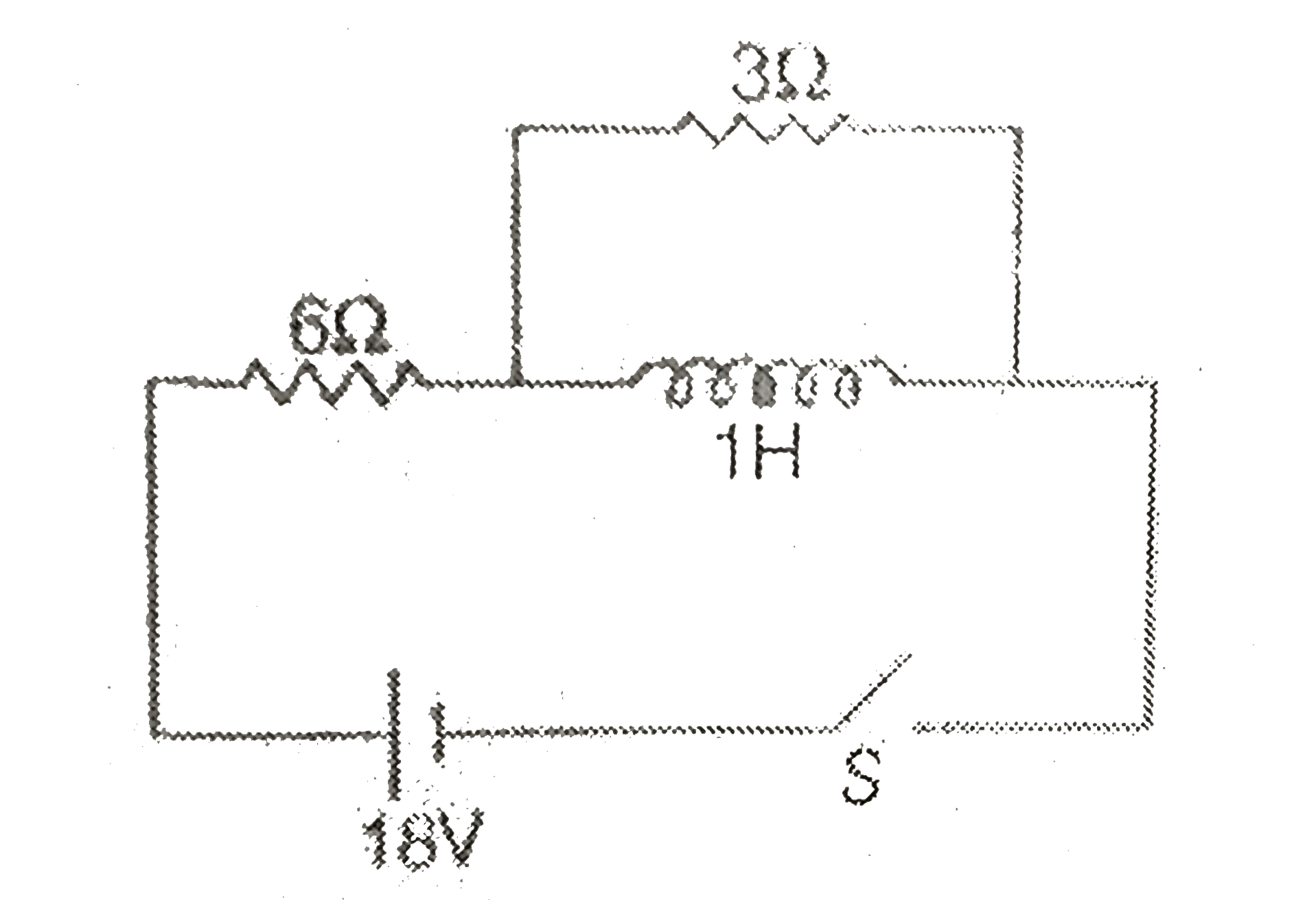
Current I from the battery at time t is given byA3(1−e−2t)B3+e−2t)C3(1-e^(-t/9))D3−e−2tIn the circuit as shown in figure the switch is closed at t=0.
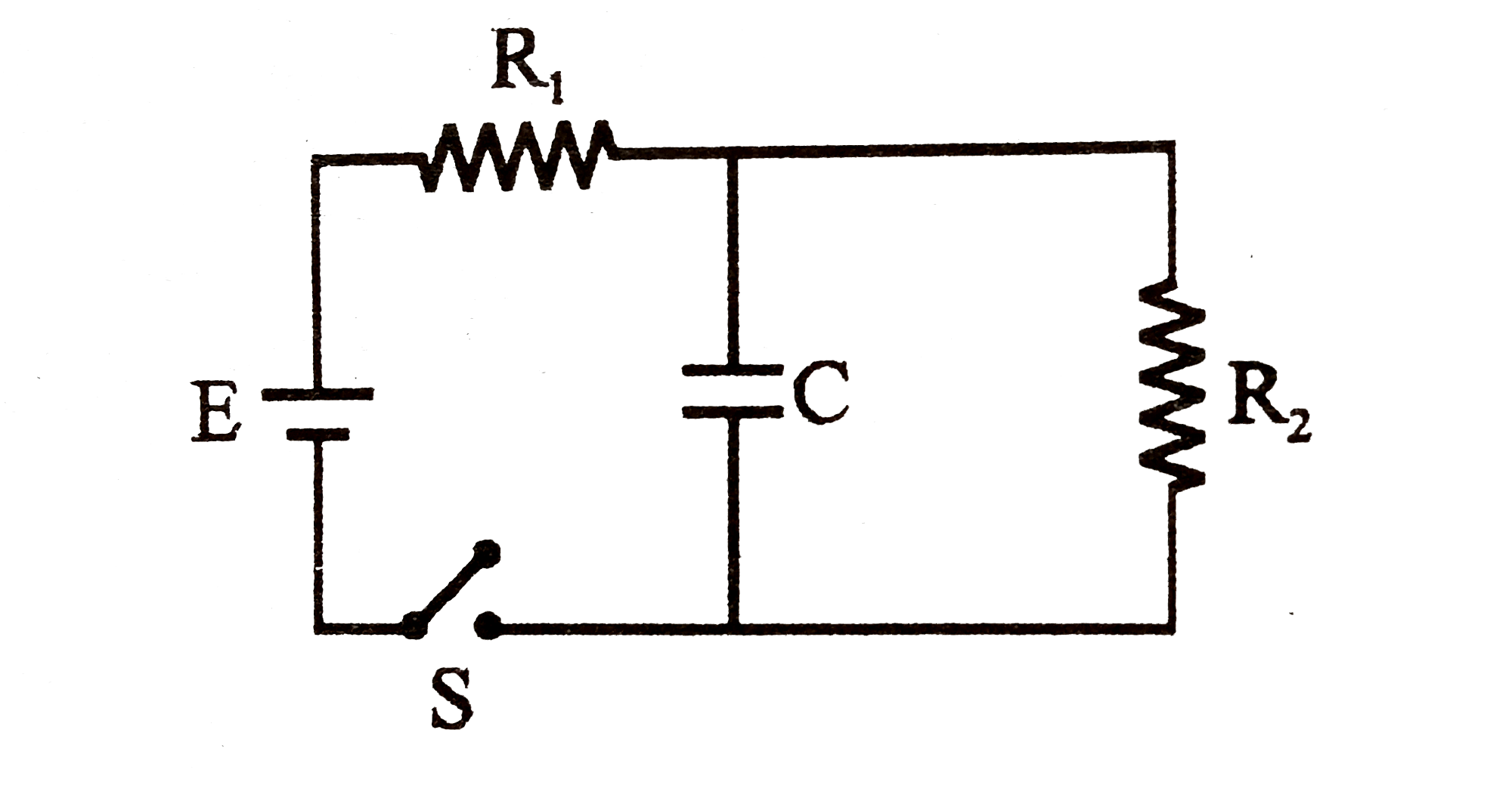
A long time after closing the switchAvoltage drop across the capacitor is EBcurent through the battery is E/R1+R2Cenegru stores in the capacitor is
12C(R2ER1+R2)2Dcurrent through the capacitor becomes zero
In the circuit diagram shown, intially there is no energy in the inductor and the capacitor. The switch is closed at t=0 . Find the current I as a function of time t .
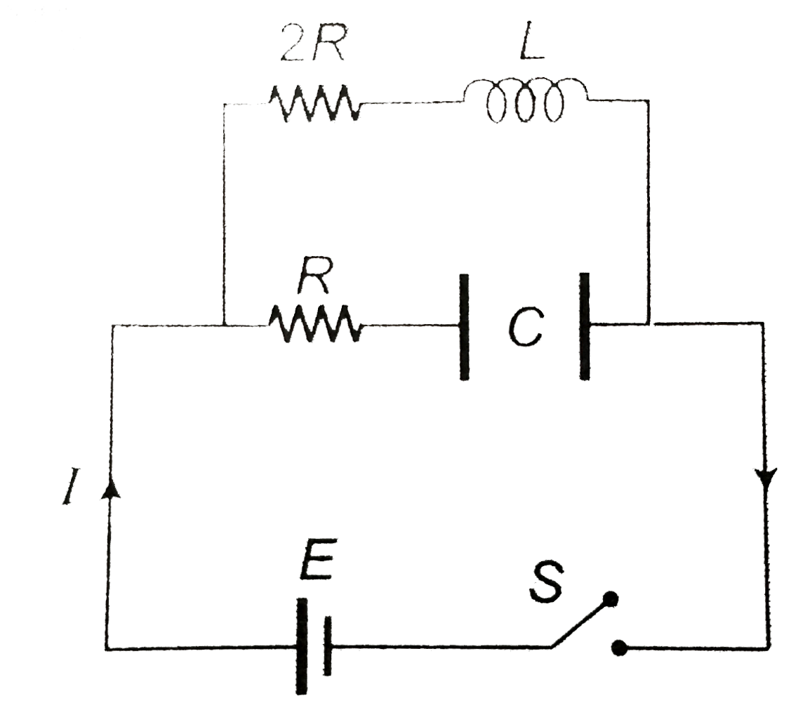
View SolutionIn the given circuit, the switch S is closed at time t = 0, then select the correct statement for current l in resistance PQ as shown in the figure.
_PHY_E05_045_Q01.png)
View SolutionIn the given circuit, the switch S is closed at time t=0 then select the correct statement for current l in resistance PQ as shown in the figure
_PHY_E05_091_Q01.png)
View SolutionIn the circuit shown. Initially the capacitor is uncharged. The switch S is closed at time t=0. Then
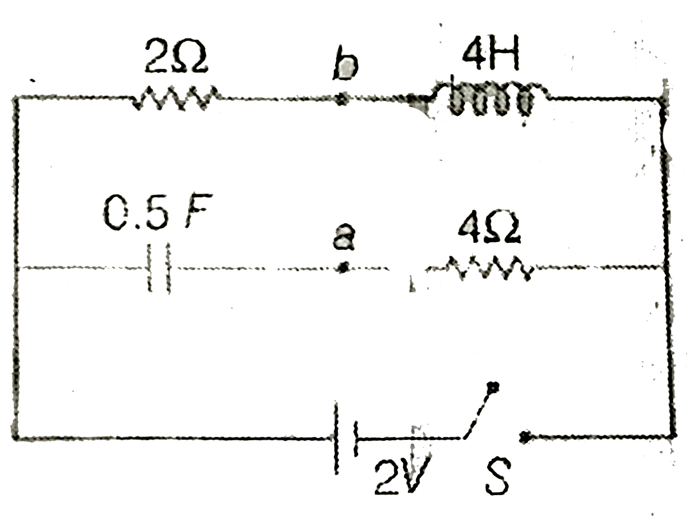
View SolutionAt t=0 , switch S is closed. Find time constant of the circuit and current through inductor as a function of time t .
View Solution

