The logic behind 'NOR' gate is that it gives
high output when both inputs are high
high output when both inputs are low
low output when both inputs are low
none of these
The correct Answer is:B
To understand the logic behind a NOR gate, we can break down the problem step by step:
Step 1: Understand the Inputs and Outputs
A NOR gate is a digital logic gate that outputs true or high (1) only when both of its inputs are false or low (0).
Step 2: Define the Inputs
Let's denote the inputs of the NOR gate as:
- Input A
- Input B
Step 3: Write the Output Expression
The output (X) of a NOR gate can be expressed in Boolean algebra as:
X=(A+B)′
This means that the output is the negation (NOT) of the logical OR of the inputs A and B.
Step 4: Create a Truth Table
To visualize how the NOR gate operates, we can create a truth table:
| A | B | A + B | X = (A + B)' |
|---|---|-------|--------------|
| 0 | 0 | 0 | 1 |
| 0 | 1 | 1 | 0 |
| 1 | 0 | 1 | 0 |
| 1 | 1 | 1 | 0 |
Step 5: Analyze the Truth Table
From the truth table, we can see:
- When both inputs A and B are 0 (low), the output X is 1 (high).
- In all other cases (when at least one input is 1), the output X is 0 (low).
Step 6: Conclusion
Therefore, the logic behind the NOR gate is that it gives a high output (1) only when both inputs are low (0).
Final Answer
The correct option is that the NOR gate gives a high output when both inputs are low.
---
A NOR gate is a digital logic gate that outputs true or high (1) only when both of its inputs are false or low (0).
Let's denote the inputs of the NOR gate as:
- Input A
- Input B
The output (X) of a NOR gate can be expressed in Boolean algebra as:
X=(A+B)′
This means that the output is the negation (NOT) of the logical OR of the inputs A and B.
To visualize how the NOR gate operates, we can create a truth table:
|---|---|-------|--------------|
| 0 | 0 | 0 | 1 |
| 0 | 1 | 1 | 0 |
| 1 | 0 | 1 | 0 |
| 1 | 1 | 1 | 0 |
From the truth table, we can see:
- When both inputs A and B are 0 (low), the output X is 1 (high).
- In all other cases (when at least one input is 1), the output X is 0 (low).
Therefore, the logic behind the NOR gate is that it gives a high output (1) only when both inputs are low (0).
The correct option is that the NOR gate gives a high output when both inputs are low.
Topper's Solved these Questions
- BOOK - ALLENCHAPTER - SEMICONDUCTORSEXERCISE - Part-3(Exercise-2)49videos
SEMICONDUCTORS
- BOOK - ALLENCHAPTER - SEMICONDUCTORSEXERCISE - Part-3(Exercise-3)27videos
SEMICONDUCTORS
- BOOK - ALLENCHAPTER - SEMICONDUCTORSEXERCISE - Part-3(Exercise-4)51videos
SEMICONDUCTORS
- BOOK - ALLENCHAPTER - PHYSICAL WORLD, UNITS AND DIMENSIONS & ERRORS IN MEASUREMENT EXERCISE - EXERCISE-IV8videos
PHYSICAL WORLD, UNITS AND DIMENSIONS & ERRORS IN MEASUREMENT
- BOOK - ALLENCHAPTER - WAVES AND OSCILLATIONSEXERCISE - Part-1(Exercise-05)[B]42videos
WAVES AND OSCILLATIONS
Similar Questions
NAND gate is-
View SolutionIt is required to design a (two -input) logic gate, using an appropriate number, of :
(a) NAND gates that gives a 'low' output only when both the inputs are 'low'.
(b) NOR gates that gives a 'high' output only when both the inputs are 'high'.
Draw the logic circuits for these two cases and write the truth table, corresponding to each of the two designs.View Solution
Knowledge Check
- Question 1 - Select One
An AND gate
Ais equivalent to a parallel switching currentBis equivalent to a series switching currentChas two outputs and one inputsDhas two outputs and two inputs
Identify the logic gate whose truth table is given below and draw its symbol :
 View Solution
The boolean equation of NOR gate is-
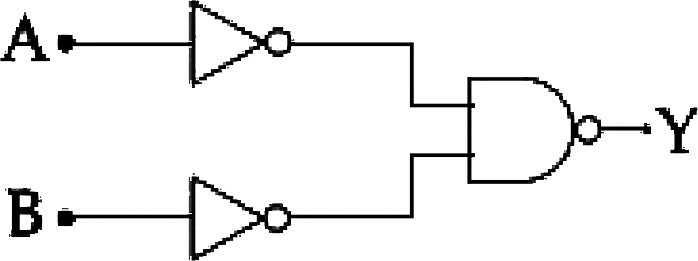
View SolutionThe logic gate equivalent to the given logic circuit is :
 View Solution
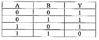
To which logic gate does the truth table given in the figure correspond?
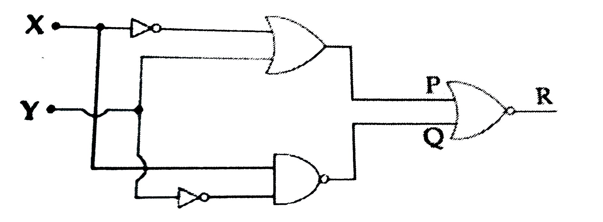
View SolutionTo get output '1' at R, for the given logic gate circuit the input values must be :
 View Solution
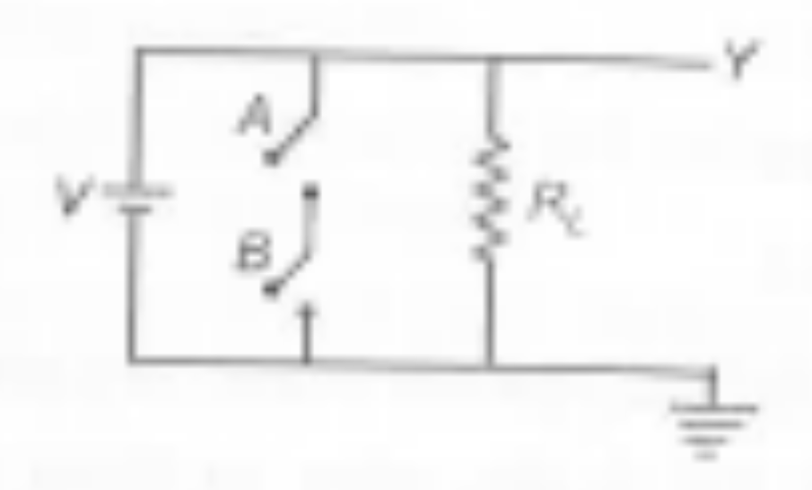
The logic gate realised from the circuit as shown in the figure is (A and B are inputs and Y is output)
 View Solution
Assertion: The logic gate NOT can be built using diode.
Reason: The output voltage and the input voltage of the diode have 180∘ phase difference.View Solution

