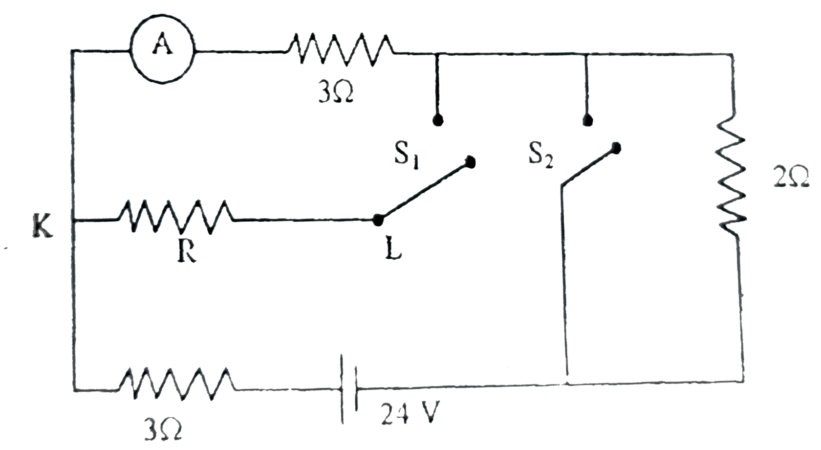
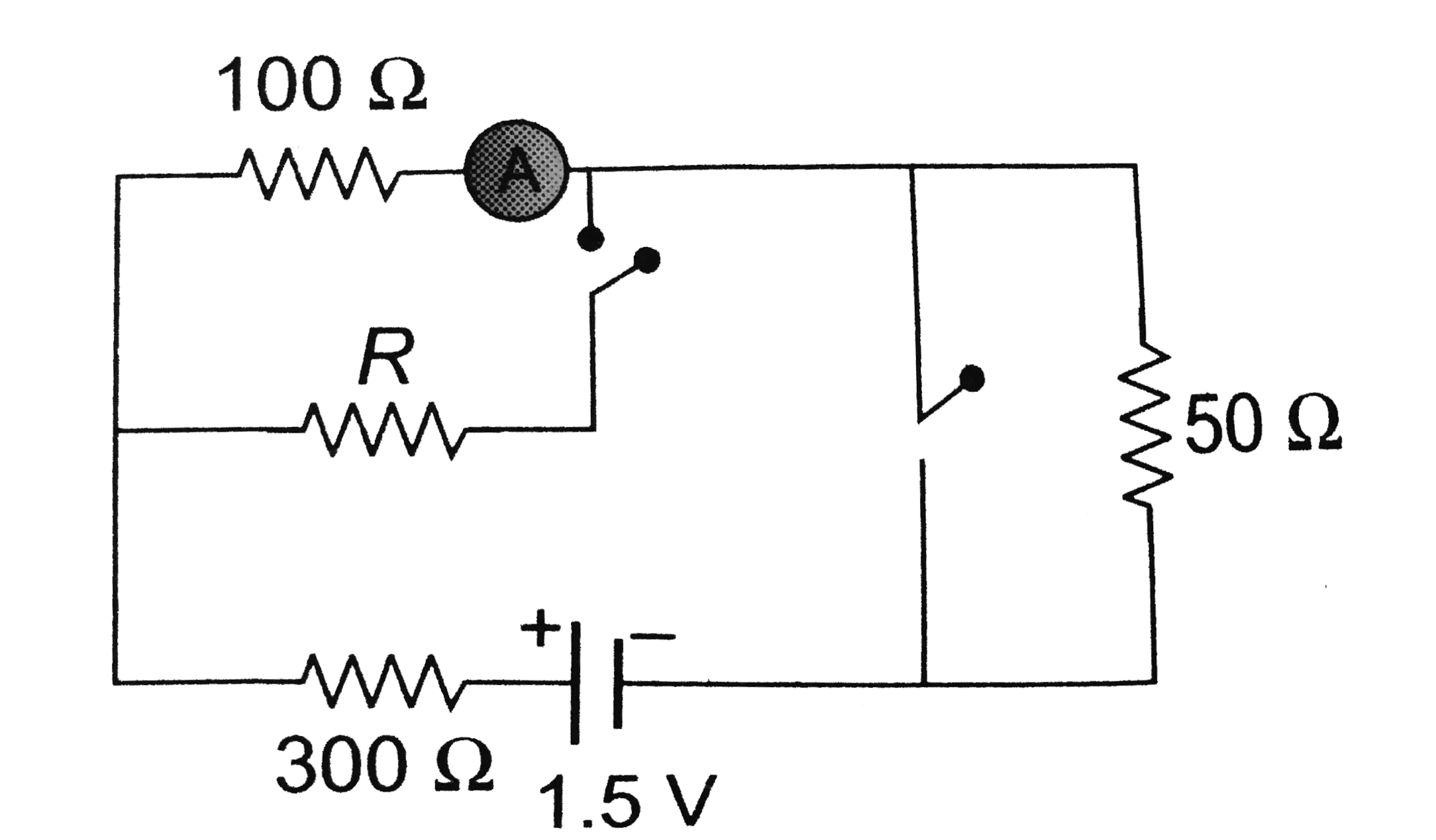
In the circuit shown in the figure, the ideal ammeter reading for current is taken
(a) with both switches open
(b) with both switches closed.
The readings are same in the cases. The value of resistance R is
2Ω
3Ω
4.5Ω
7.5Ω
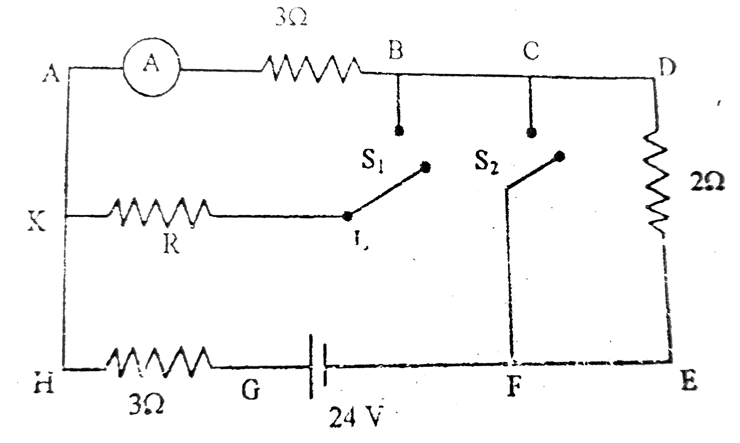
When both switches are open, then reading of ammeter is 24/3=3A
When both switches are closed.
VAB=9V⇒VHG=15⇒ So current through R is 2A.
Hence R=9/2=4.5Ω
Similar Questions
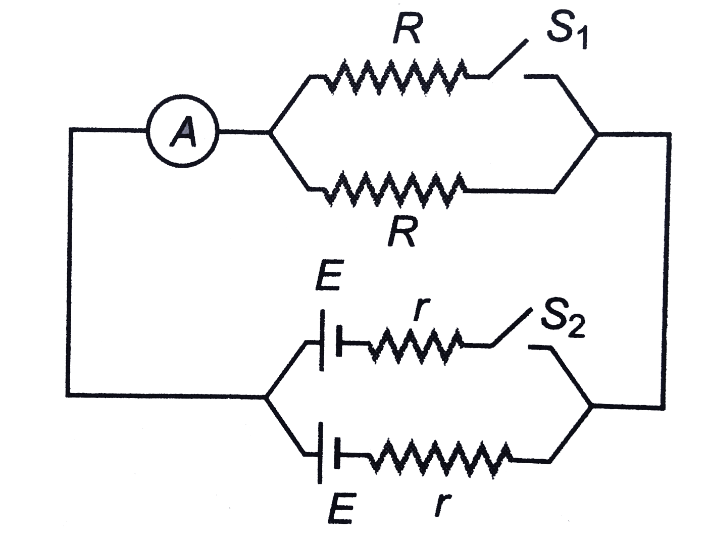
In the circuit shown in figure, reading of ammeter will
View Solution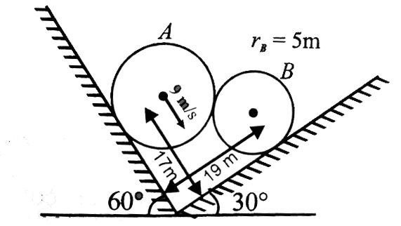
System is shown in the figure. Velocity of sphere A is 9 ms. Find the speed of sphere B.
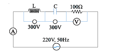
View SolutionIn the circuit shown in figure, what will be the readings of voltmeter and ammeter?
View SolutionIn the circuit shown in figure the reading of ammeter is the same with both switches open as with both closed. Then find the resistance R. (ammeter is ideal).
View SolutionIn the circuit shown in figure the reading of ammeter is the same with both switches open as with both closed. Then find the resistance R. (ammeter is ideal).

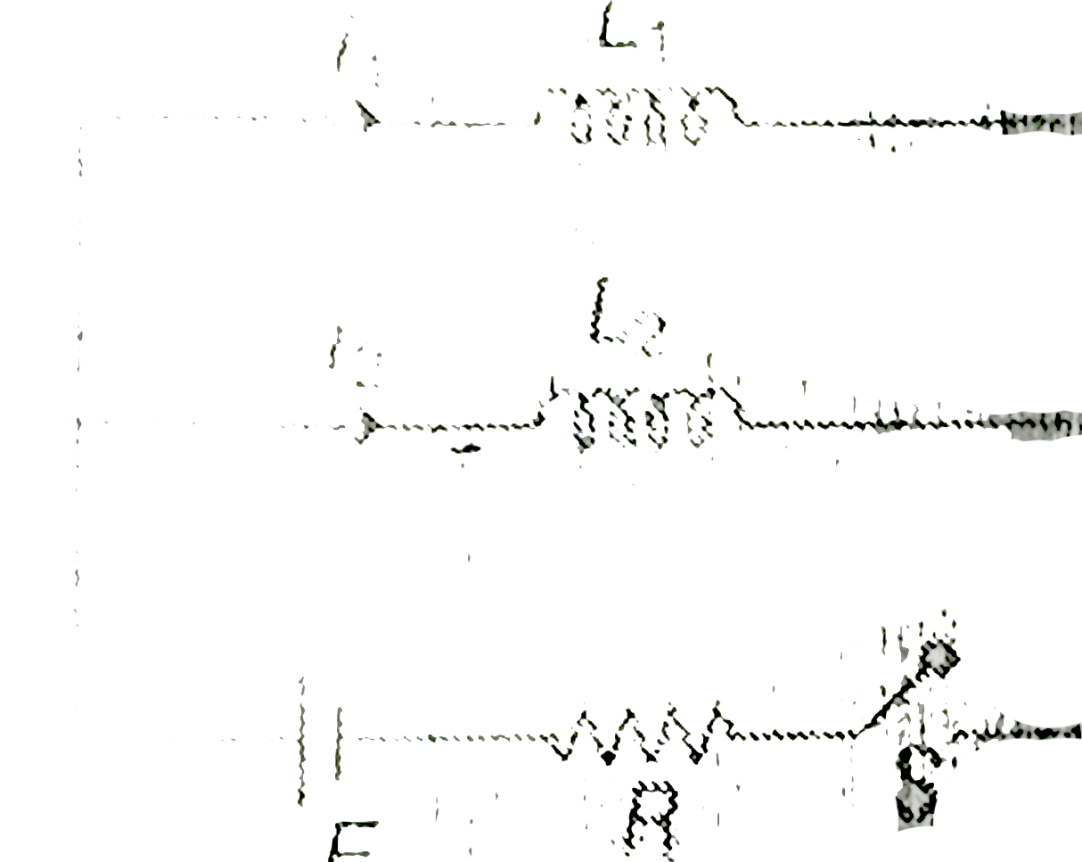
View SolutionIn the circuit shown in the figure The steady state currents i1andi2 in the coils after the switch S is closed are
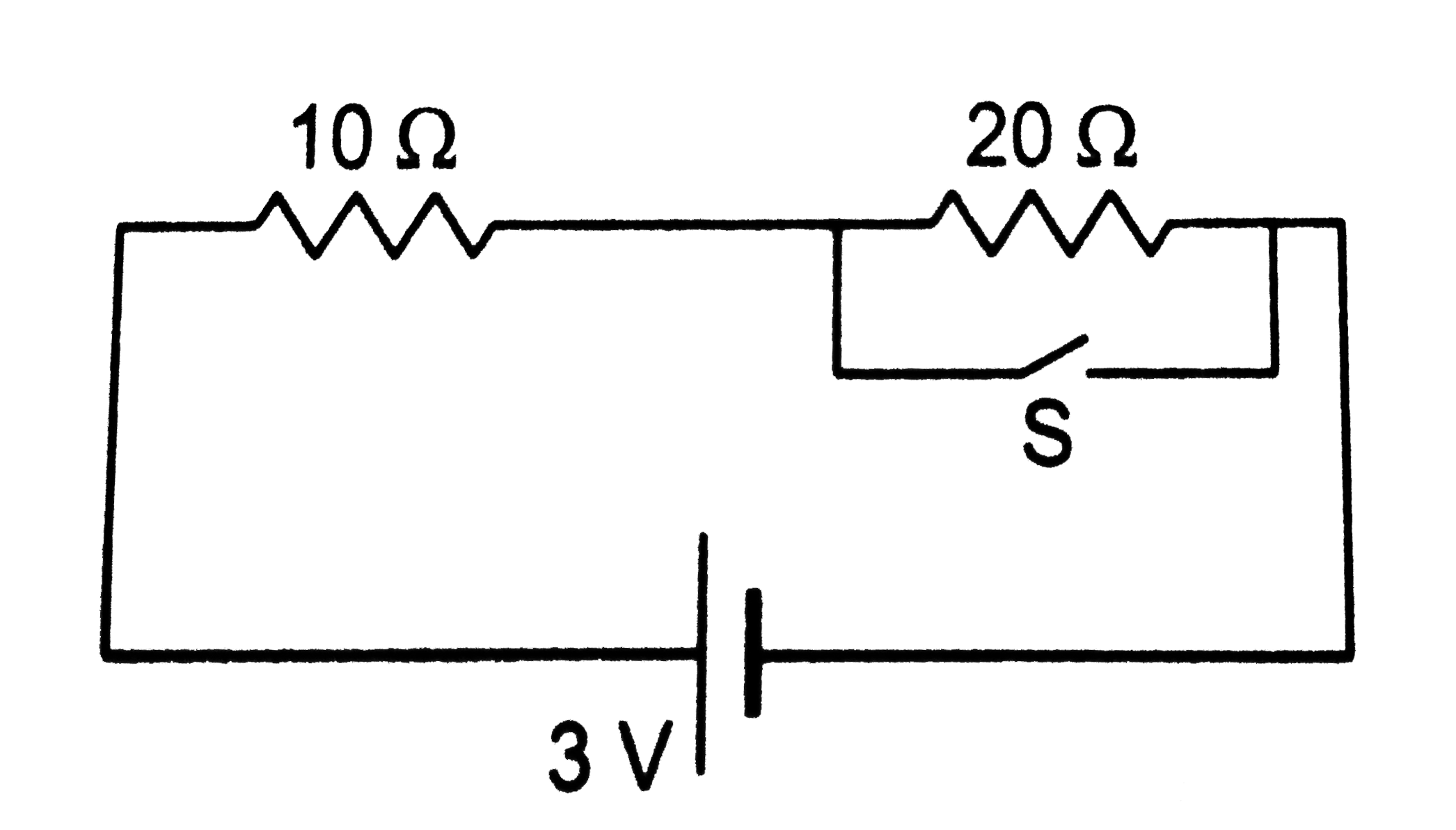
View SolutionConsider the circuit shown in figure.Find the current through the10(Ω)resistor when the switch S is (a)open (b)closed .
View SolutionIn the circuit shown, A and V are ideal ammeter and voltmeter respectively. Reading of the voltmeter will be

View SolutionIn the circuit shown in figure switch S is closed at time t=0
Current I from the battery at time t is given by
View SolutionThe reading of ammeter in the circuit shown in the figure is
_PHY_E05_032_Q01.png)
View Solution
