For the circuit shown in figure when R=2Ω, V=0.75 volts, when R=3Ω, V = 0.9 Volts when R=4Ω V=V1 where V1equals (in volts) andI1(in amp)
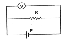
11=1.2A
V1=1.5V
I1=1.0A
V1=1.0V
The correct Answer is:C, D
Step by step video & image solution for For the circuit shown in figure when R = 2Omega, V=0.75 volts, when R=3Omega, V = 0.9 Volts when R = 4Omega V=V_(1) where V_(1)equals (in volts) andI_(1) (in amp) by Physics experts to help you in doubts & scoring excellent marks in Class 12 exams.
Updated on:21/07/2023Similar Questions
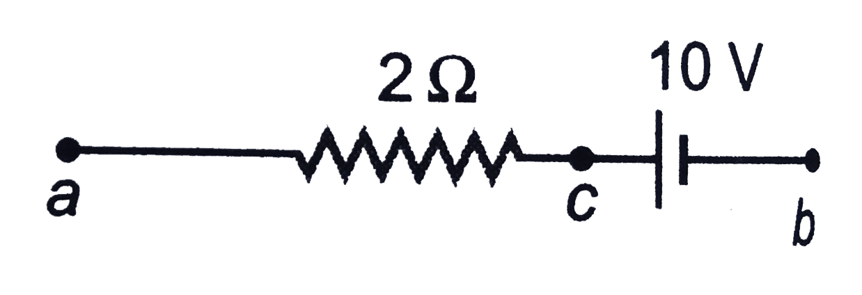
In the circuit shown in figure it is given that Vb−Va=2 volt. Choose the correct options
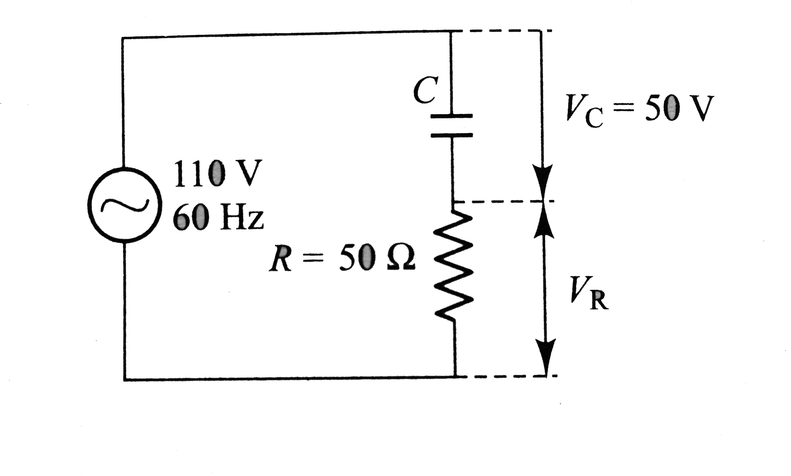
View SolutionIn the circuit given in fig. (VC)=50VandR=50Ω. The values of C and (VR) are
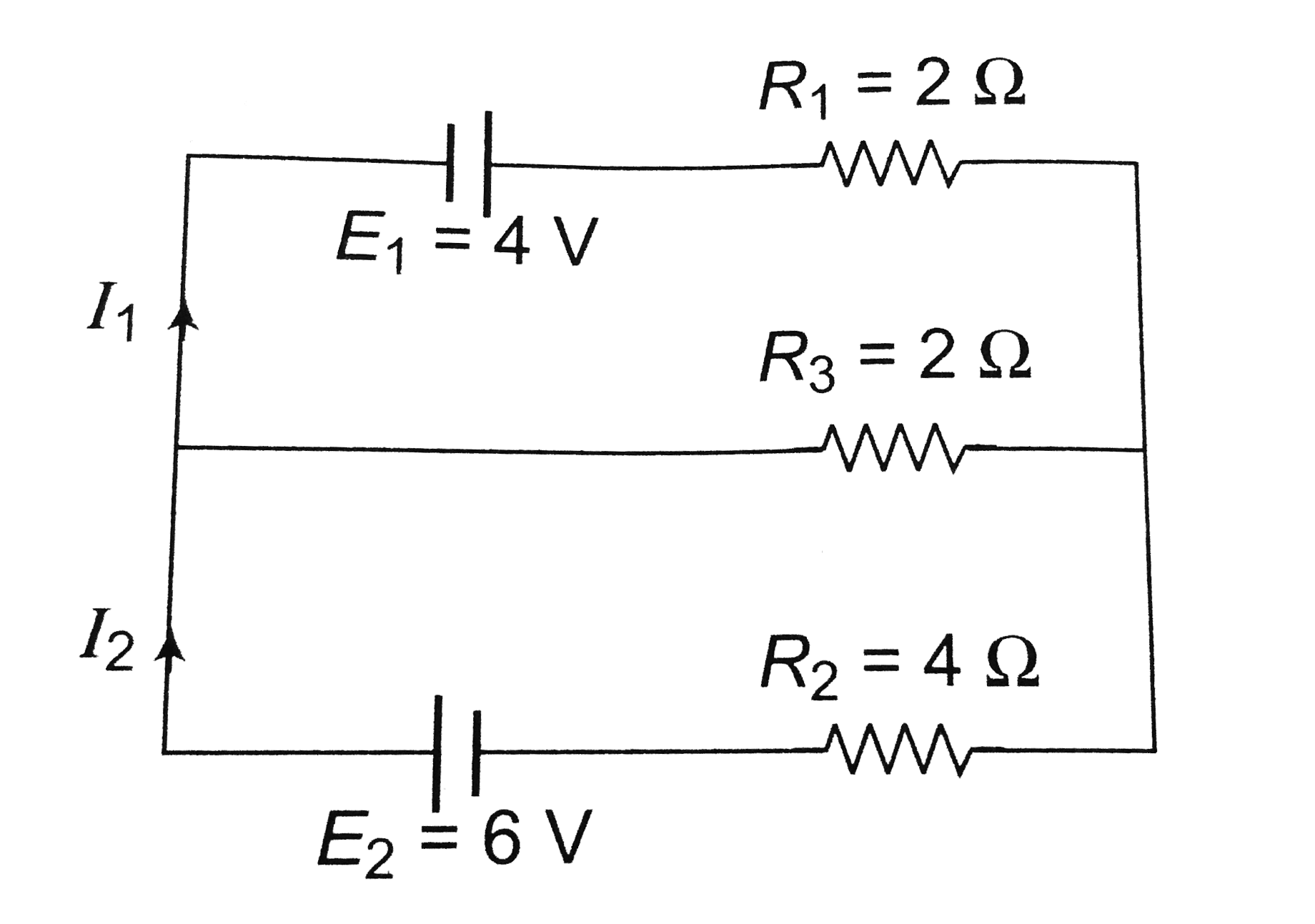
View SolutionIn the circuit shown below E1=4.0V,R1=2Ω,E2=6.0V,R2=4Ω and R3=2Ω. The current I1 is
View SolutionIn the circuit shown in figure

E1=10V,E2=4V,r1=r2=1Ω and R=2Ω.
Find the potential difference across battery 1 and battery 2.
View SolutionIn the circuit shown in figure

E1=10V,E2=4V,r1=r2=1Ω and R=2Ω.
Find the potential difference across battery 1 and battery 2.
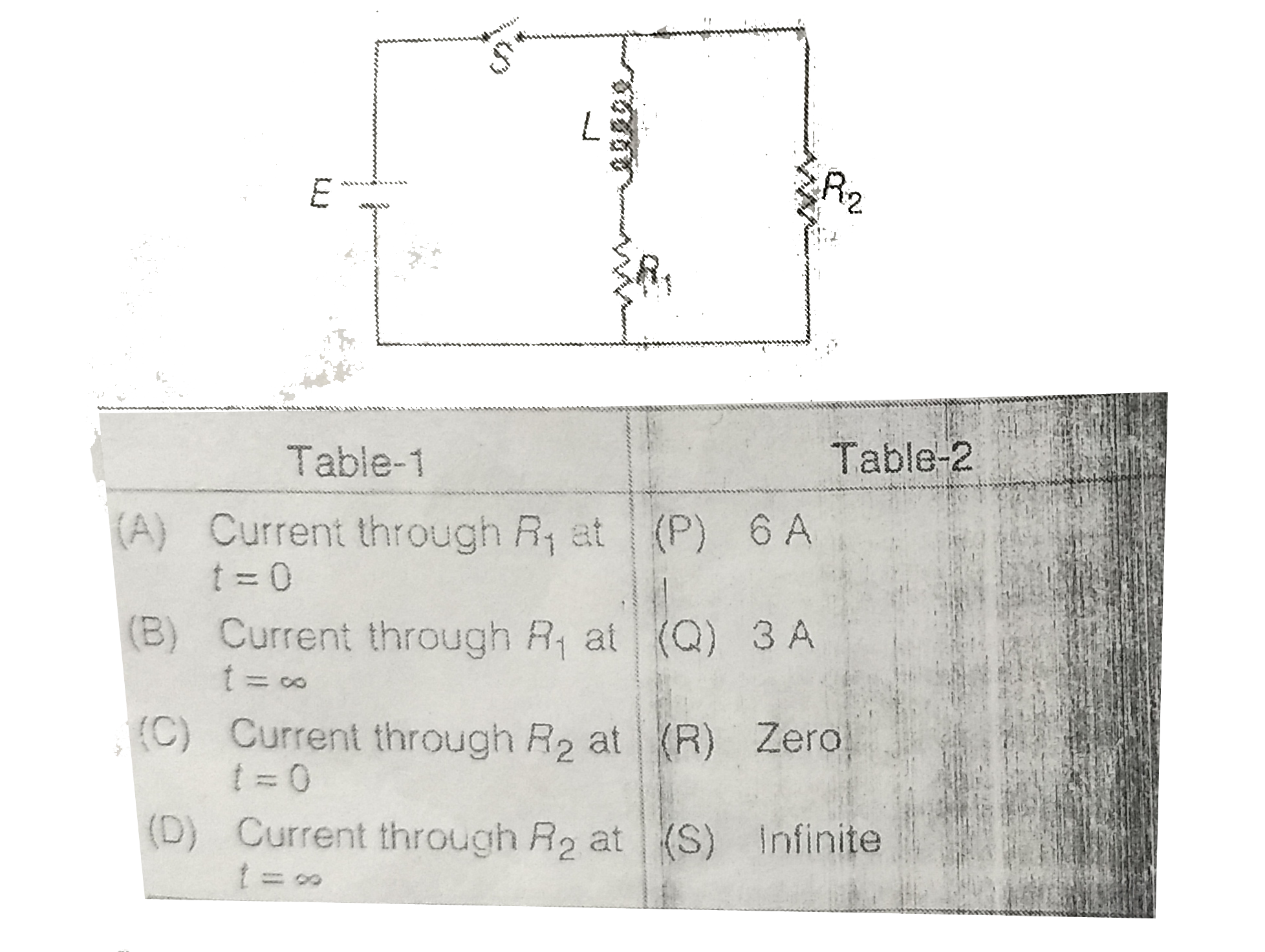
View SolutionIn the circuit diagram shown in Figure E=18V , L=2H, R1=3Ω,R2=6Ω. Switch S is closed at t=0 Match the following:
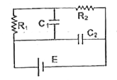
View SolutionIn the circuit shown in figure, R(1)=1Ω,R2=2Ω,C1=1μF,C2=2μF and E=6V. Calculate charge on each capacitor in steady state
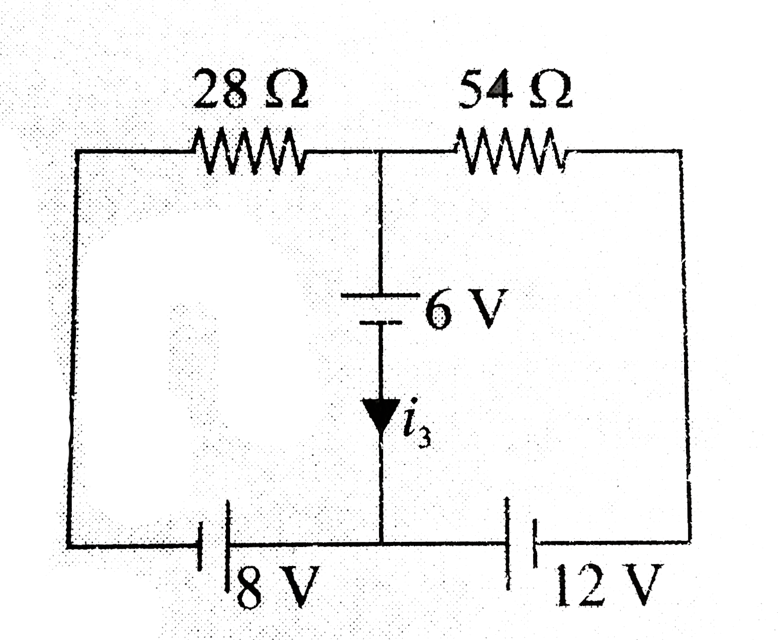
View SolutionIn the following circuit ,E1=4V,R1=2Ω,
E2=6V,R2=2Ω,andR3=4Ω. Find the currents i1andi2
View SolutionConsider the circuit shown in the figure, the cell is ideal. The readings of the ideal voltmeters V1 and V2 in volts are respectively.

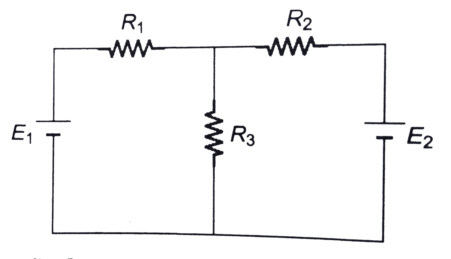
View SolutionIn the circuit shown in figure E1=7V,E2=1V,R1=2Ω,R2=2Ω and R3=3Ω respectively. Find the power supplied by the two batteries.
View Solution
