A number of resistors R1,R2,R3... are connected in series such that R, is the equivalent resistance of series combination. A current I is flowing in the circuit due to a potential V applied across the circuit. V1,V2,V3.... are potential difference across R1,R2,R3.... respectively. Choose the incorrect statement
Same current I will flow through each resistor
V1+V2+V3+….=V
V1=(R1RS)V,V2=(R2RS)V,V3=(R3RS)V….
V1=(RSR1)V,V2=(RSV2)V,V3=(RSR3)V…..
The correct Answer is:D
To solve the problem, we need to analyze the statements related to resistors connected in series and determine which one is incorrect.
1. Understanding Series Resistors:
- When resistors R1,R2,R3,… are connected in series, the total or equivalent resistance Rs is given by:
Rs=R1+R2+R3+…
2. Current in Series Circuit:
- In a series circuit, the same current I flows through each resistor. Therefore, we can state:
I=I1=I2=I3=…
- This means that the current flowing through each resistor is identical.
3. Voltage Across Each Resistor:
- The potential difference across each resistor can be calculated using Ohm's law:
V1=I⋅R1,V2=I⋅R2,V3=I⋅R3
- The total voltage V across the series circuit is the sum of the individual voltages:
V=V1+V2+V3+…
4. Using Kirchhoff's Voltage Law (KVL):
- According to KVL, the sum of the potential differences in a closed loop is equal to the total voltage supplied. Thus:
V−V1−V2−V3−…=0⟹V=V1+V2+V3+…
5. Identifying the Incorrect Statement:
- Based on the above analysis, we can evaluate the provided statements.
- The correct statements are:
- The current is the same through each resistor (True).
- The total voltage is equal to the sum of the individual voltages (True).
- The equivalent resistance is the sum of the individual resistances (True).
- The incorrect statement would typically suggest a relationship that contradicts these principles, such as suggesting that the voltage across one resistor is somehow related to the equivalent resistance in a way that does not hold true.
Conclusion:
The incorrect statement is identified as option D (as per the video), which does not conform to the principles of series circuits.
- When resistors R1,R2,R3,… are connected in series, the total or equivalent resistance Rs is given by:
Rs=R1+R2+R3+…
- In a series circuit, the same current I flows through each resistor. Therefore, we can state:
I=I1=I2=I3=…
- This means that the current flowing through each resistor is identical.
- The potential difference across each resistor can be calculated using Ohm's law:
V1=I⋅R1,V2=I⋅R2,V3=I⋅R3
- The total voltage V across the series circuit is the sum of the individual voltages:
V=V1+V2+V3+…
- According to KVL, the sum of the potential differences in a closed loop is equal to the total voltage supplied. Thus:
V−V1−V2−V3−…=0⟹V=V1+V2+V3+…
- Based on the above analysis, we can evaluate the provided statements.
- The correct statements are:
- The current is the same through each resistor (True).
- The total voltage is equal to the sum of the individual voltages (True).
- The equivalent resistance is the sum of the individual resistances (True).
- The incorrect statement would typically suggest a relationship that contradicts these principles, such as suggesting that the voltage across one resistor is somehow related to the equivalent resistance in a way that does not hold true.
The incorrect statement is identified as option D (as per the video), which does not conform to the principles of series circuits.
Similar Questions
A 6 V, 12 W lamp is connected in series with a resistor R and a source of voltage 12 V.
What is the current flowing through the circuit?
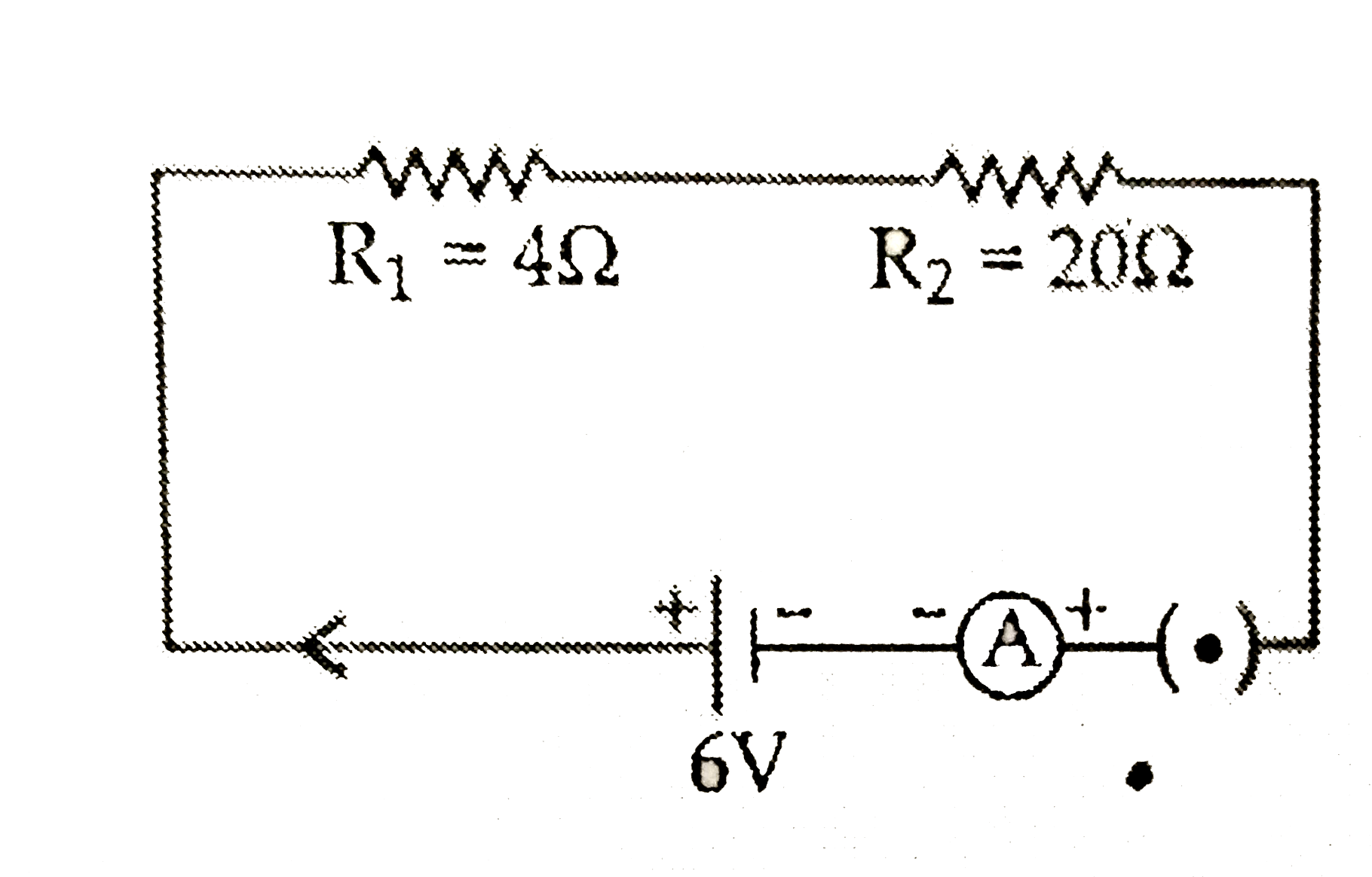
View SolutionIn the given circuit, calculate -

(a) the total resistance of the circuit,
(b) the current through the circuit, and
(c) the potential differences across R1andR2
View Solution
Knowledge Check
Two resistors of resistances R1=(300±3)Ω and R2=(500±4)Ω are connected in series. The equivalent resistance of the series combination is
A(800±1)ΩB(800±7)ΩC(200±7)ΩD(200±1)Ω
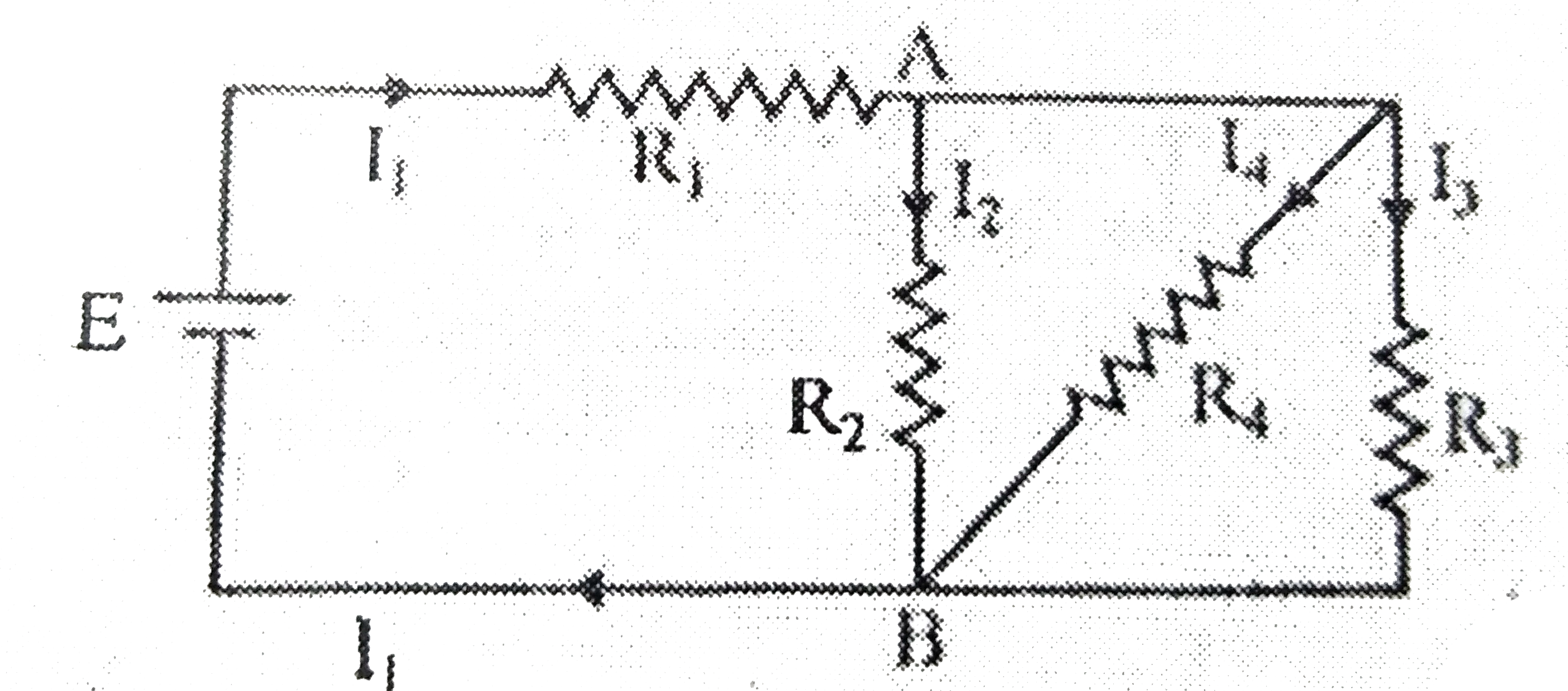
In the circuit shown, R1=2Ω,R2=R3=10ΩandE=6V. Work out the equivalent resistance of the circuit and the current in each resistor.

View SolutionA resistor of 6 Ω is connected in series with another resistor of 4 Ω. A potential difference of 20 V is applied across the combination. Calculate :
the current in the circuit,
View SolutionIn an ac circuit the potential differences across an inductance and resistance joined in series are, respectively, 16 V and 20 V. The total potential difference across the circuit is
View SolutionIn an ac circuit the potential differences across an inductance and resistance joined in series are, respectively, 16 V and 20 V. The total potential difference across the circuit is
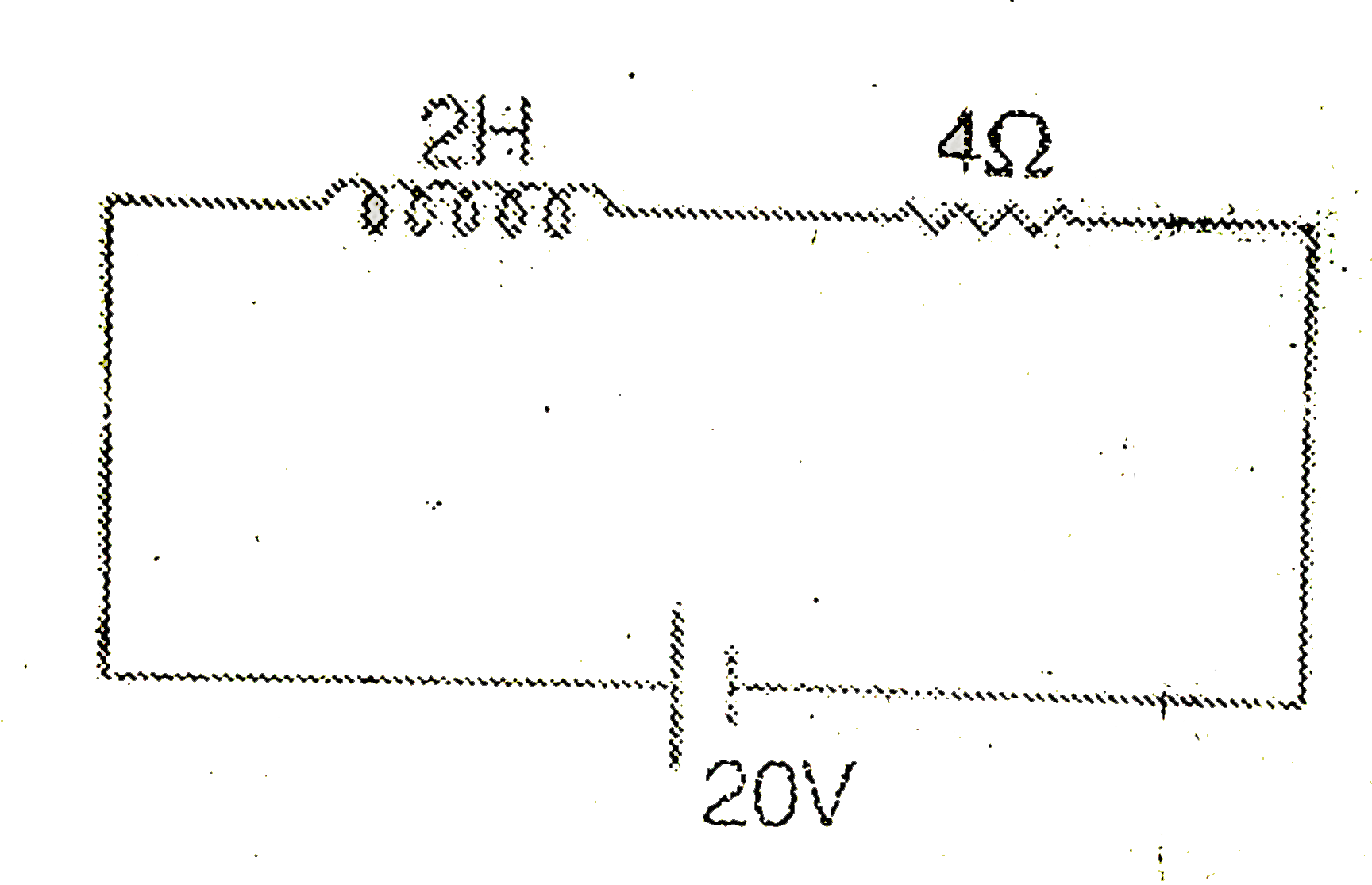
View SolutionIn the L-R circuit as shown in figure, potential difference across the resistance at some instant is 4 V. Then

View SolutionIn a series L.C.R. circuit, the potential drop across L, C and R respectively are 40V, 120V and 60V . Them the source voltage is
View SolutionIn the circuit shown, R1=2Ω,R2=R3=10Ω,R4=20ΩandE=6V. Work out the equivalent resistance of the circuit and the current in each resistor.

View Solution
