Four capacitors of capacitanes C1=iμF,C2μF,C3=3μFandC4=4μF are connected as shown in the figure. Find the potential difference (in volt) across C3 when switch S is closed.
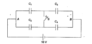
When switch S is open, the circuit is,
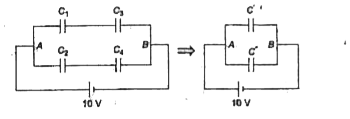
C1andC2 are in series, charge on C1 charge on C3⇒Q (say) and potential difference across the combination of C1andC3 is 10 V.
∴Q=C1V1=C3V3⇒C1V1=C3V3, ⇒V1=3V3
Alos V1+V3=10, Hence V3=2.5V
WHen switch S is closed, the circuit is shown as
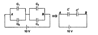
C.=1+2=3μF,C..=3+4=7μF
Since C. and C.. are in series, the charge in C. is equal to change on C...
on C.V.=C..V..⇒3V.=7V..
⇒V.+V..=10⇒7V..3+V..⇒10, ⇒V..=3V
Similar Questions
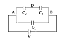
Three capacitors C1=2μF,C26μFandC3=12μFare connected as shown in figure. Find the ratio of the charges on capacitors C1,C2andC3 respectively :
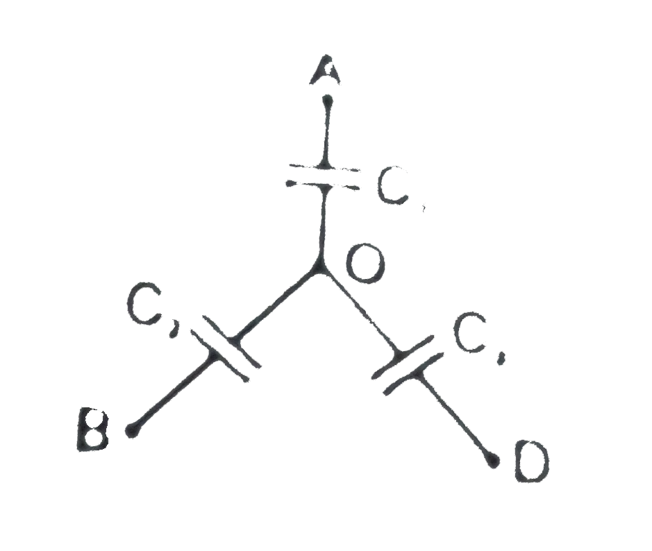
View SolutionThree uncharged capacitors of capacitance C1=1μF,C2=2μF and C3=3μF are connected as shown in the figure. The potential of point A, B and D are 10 volt, 25 volt and 20 volt respectively. Determine the potential at point O.
View Solution
Knowledge Check
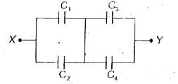
In the circuit shown below C1=10μF, C2=C3=20μF, and C4=40μ F. if the charge on C1 is 20μC then potential difference between X and Y is
 A2 VB3 VC6 VD3.5 V
In the arrangement shown in , the switch S is find
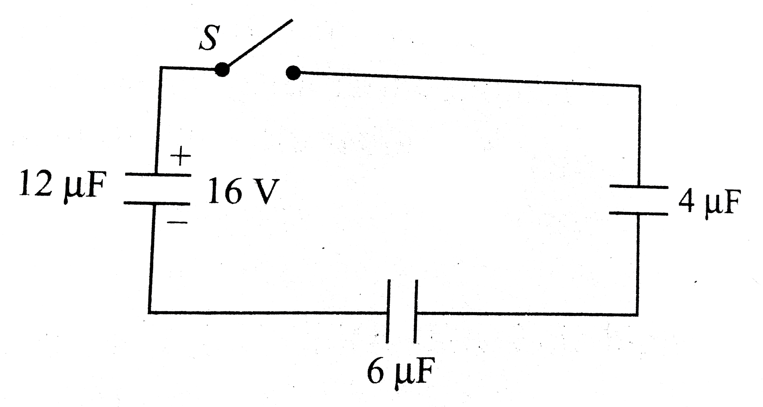 the final potential difference across the 4μF capacitorA12VB8VC20VD32V
Three uncharged capacitors of capacitance C1=1μF,C2=2μF and C3=3μF are connected as shown in the figure. The potential of point A, B and D are 10 volt, 25 volt and 20 volt respectively. Determine the potential at point O.

View SolutionThree capacitors of capacitance C1=3μf,C2=6μfandC3=10μf, are connected to a 10V battery as shown in Figure 3 below
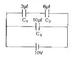
Calculate:
Equivalent capacitance
View SolutionIn the circuit shown below C1=10μF, C2=C3=20μF, and C4=40μ F. if the charge on C1 is 20μC then potential difference between X and Y is

View SolutionThree capacitors of capacitance C1=3μf,C2=6μfandC3=10μf, are connected to a 10V battery as shown in Figure 3 below
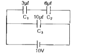
Calculate:
Electrostatic potential energy stored in the system
View SolutionIn the circuit shown in the following the potential difference across the 3μF capacitor is
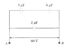
View SolutionIn the arrangement shown in , the switch S is find
 the final potential difference across the 4μF capacitor
View Solution
