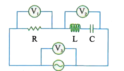
Assertion (A): For phenomena of resonance both L·& Care to be present in circuit.
Reason (R): Voltage across L and C cancel each other and the total source voltage appearing across our causes resonance.
Both (A) and (R) are true and (R) is the correct explanation of (A).
Both (A) and (R) are true but (R) is not the correct explanation of (A).
(A) is true but (R) is false.
(A) is false and (R) is also false.
To analyze the assertion and reason provided in the question, we need to break down the concepts of resonance in an RLC circuit (which includes a resistor R, an inductor L, and a capacitor C).
1. Understanding Resonance:
- In an RLC circuit, resonance occurs when the inductive reactance (XL) is equal to the capacitive reactance (XC). This condition can be mathematically expressed as:
XL=XC
- Inductive reactance is given by XL=2πfL and capacitive reactance is given by XC=12πfC, where f is the frequency of the AC source.
2. Condition for Resonance:
- At resonance, the total impedance (Z) of the circuit is minimized. The impedance can be expressed as:
Z=R(at resonance, since XL=XC)
- This means that the circuit behaves as a purely resistive circuit at resonance.
3. Voltage Across L and C:
- When resonance occurs, the voltages across the inductor (V_L) and the capacitor (V_C) are equal in magnitude but opposite in phase. Therefore, they cancel each other out:
VL+VC=0⇒Vtotal=VR
- This implies that the entire source voltage appears across the resistor (R).
4. Conclusion:
- The assertion (A) is correct because both L and C are indeed necessary for resonance to occur in an RLC circuit.
- The reason (R) is also correct as it accurately describes the cancellation of voltages across L and C, leading to the total source voltage appearing across R.
5. Final Answer:
- Both the assertion (A) and the reason (R) are correct, and the reason correctly explains the assertion.
- In an RLC circuit, resonance occurs when the inductive reactance (XL) is equal to the capacitive reactance (XC). This condition can be mathematically expressed as:
XL=XC
- Inductive reactance is given by XL=2πfL and capacitive reactance is given by XC=12πfC, where f is the frequency of the AC source.
- At resonance, the total impedance (Z) of the circuit is minimized. The impedance can be expressed as:
Z=R(at resonance, since XL=XC)
- This means that the circuit behaves as a purely resistive circuit at resonance.
- When resonance occurs, the voltages across the inductor (V_L) and the capacitor (V_C) are equal in magnitude but opposite in phase. Therefore, they cancel each other out:
VL+VC=0⇒Vtotal=VR
- This implies that the entire source voltage appears across the resistor (R).
- The assertion (A) is correct because both L and C are indeed necessary for resonance to occur in an RLC circuit.
- The reason (R) is also correct as it accurately describes the cancellation of voltages across L and C, leading to the total source voltage appearing across R.
- Both the assertion (A) and the reason (R) are correct, and the reason correctly explains the assertion.
Topper's Solved these Questions
- SAMPLE PAPER 9 BOOK - EDUCART PUBLICATIONCHAPTER - SAMPLE PAPER 9 EXERCISE - SECTION - C
3 Videos
- SAMPLE PAPER 9 BOOK - EDUCART PUBLICATIONCHAPTER - SAMPLE PAPER 9 EXERCISE - SECTION - C
3 Videos
- SAMPLE PAPER 7BOOK - EDUCART PUBLICATIONCHAPTER - SAMPLE PAPER 7EXERCISE - SECTION-C
6 Videos
- SAMPLE PAPER SELF- ASSESSMENT -(10)BOOK - EDUCART PUBLICATIONCHAPTER - SAMPLE PAPER SELF- ASSESSMENT -(10)EXERCISE - SECTION-B
17 Videos
Similar Questions
An LCR series ac circuit is at resonance with 10 V each across L.C and R. If the resistance is halved, the respective voltages across L,C and R are

View SolutionAn LCR series ac circuit is at resonance with 10 V each across L.C and R. If the resistance is halved, the respective voltages across L,C and R are

View Solution
Knowledge Check
Assertion : Resonance is exhibited by a circuit only if both L and C are present in the circuit.
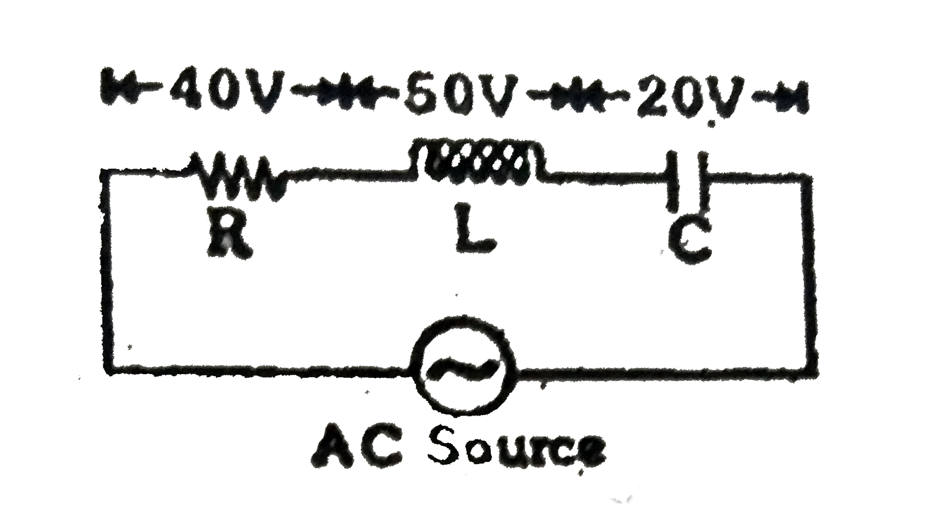
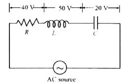
Reason : Only then the voltage across L and C cancel each other, both being out of phase.AIf both assertion ans reason are true ans reaason is the correct explanation of assertion.BIf both assertion and reason are true but reason is not the correct explanation of assertion.CIf assertion istrue but reason is false.DIf both assertion and reason are false.In series LCR circuit, the voltages across R, L and C are shown in the figure. The voltage of applied source
 A110 VB10 voltC50 voltD70 volt
In an LCR series circuit the voltages across R,L and C at resonance are 40Vand60V respectively the applied voltage is .
A60VB40VC160VD√(40)2+(120)2V
In series LCR circuit, the voltages across R, L and C shown in figure. The voltage of applied source is

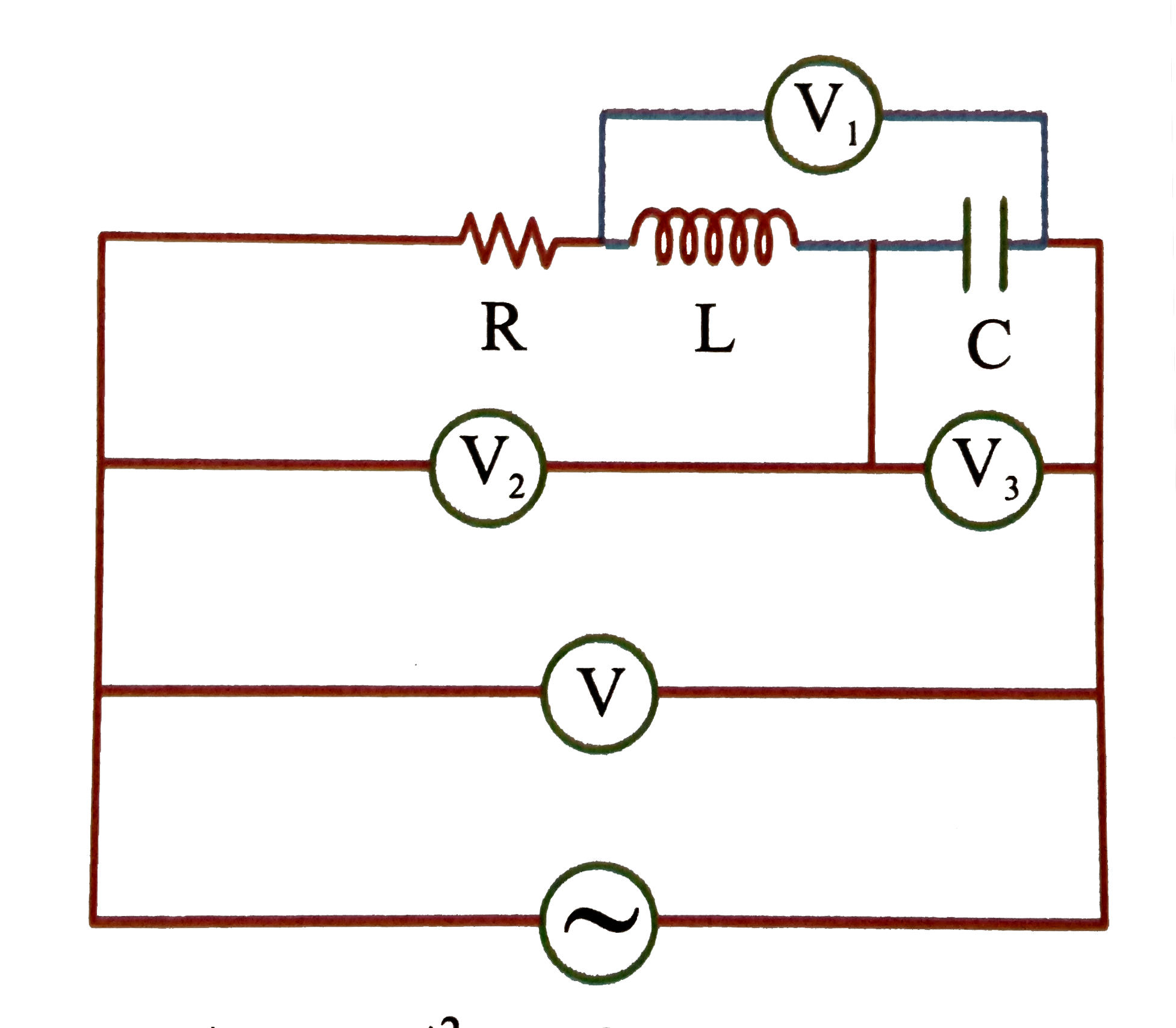
View SolutionAt resonance of the given series R−L−C circuit:

View SolutionThe ratio of voltage across inductor/condenser to the voltage across resistor in a series resonance circuit is
View SolutionPhase difference between voltages across L and C in series is
View SolutionAn LCR series ac circuit is at resonance with 10 V each across L, C and R. If the resistance is halved, the respective voltage across L, C and R are
View Solution
