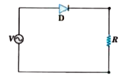
A full wave rectifier circuit consists of two p-n junction diodes, a centre-tapped transformer, capacitor and a load resistance, Which of these components remove the ac ripple from the rectified output?
p-n junction diodes
Capacitor
Load resistance
A centre-tapped transformer
To solve the question regarding which component removes the AC ripple from the rectified output in a full wave rectifier circuit, we can follow these steps:
1. Understand the Components:
- A full wave rectifier circuit typically consists of two p-n junction diodes, a center-tapped transformer, a capacitor, and a load resistance.
- Each component has a specific role in the rectification process.
2. Identify the Function of Each Component:
- P-N Junction Diodes: These diodes are responsible for allowing current to flow in one direction, effectively converting AC to DC.
- Center-Tapped Transformer: This component steps down the voltage and provides the necessary phase shift for the diodes to work in a full-wave configuration.
- Capacitor: The capacitor is used to smooth out the fluctuations in the output voltage, which is known as the AC ripple.
- Load Resistance: This is where the output DC voltage is utilized, but it does not play a role in filtering the ripple.
3. Determine Which Component Removes AC Ripple:
- The AC ripple refers to the residual periodic variation (the AC component) in the output voltage after rectification.
- The capacitor charges during the peaks of the rectified output and discharges during the troughs, thereby smoothing out the voltage and reducing the ripple.
4. Conclusion:
- Based on the functions of the components, the capacitor is the component that removes the AC ripple from the rectified output.
Final Answer:
The component that removes the AC ripple from the rectified output is the capacitor.
- A full wave rectifier circuit typically consists of two p-n junction diodes, a center-tapped transformer, a capacitor, and a load resistance.
- Each component has a specific role in the rectification process.
- P-N Junction Diodes: These diodes are responsible for allowing current to flow in one direction, effectively converting AC to DC.
- Center-Tapped Transformer: This component steps down the voltage and provides the necessary phase shift for the diodes to work in a full-wave configuration.
- Capacitor: The capacitor is used to smooth out the fluctuations in the output voltage, which is known as the AC ripple.
- Load Resistance: This is where the output DC voltage is utilized, but it does not play a role in filtering the ripple.
- The AC ripple refers to the residual periodic variation (the AC component) in the output voltage after rectification.
- The capacitor charges during the peaks of the rectified output and discharges during the troughs, thereby smoothing out the voltage and reducing the ripple.
- Based on the functions of the components, the capacitor is the component that removes the AC ripple from the rectified output.
The component that removes the AC ripple from the rectified output is the capacitor.
Topper's Solved these Questions
Similar Questions
Knowledge Check
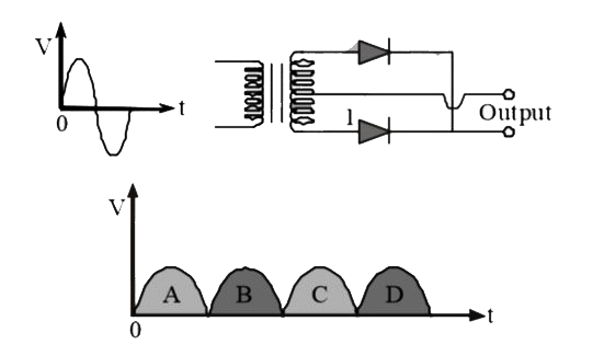
A full wave rectifier circuit along with the input and output are shown in Fig. the concentrations from the diode I is (are)
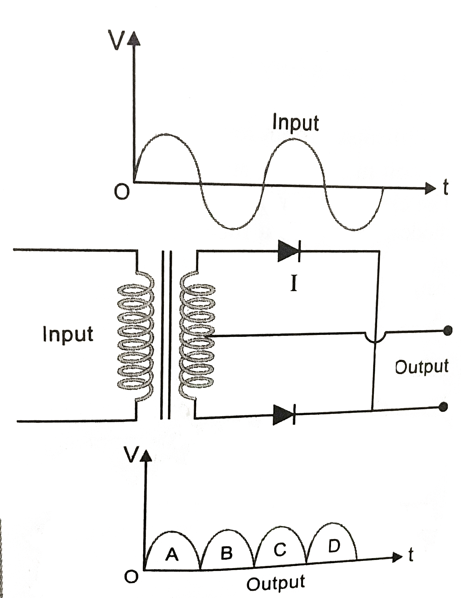 ACBA, CCB, DDA, B, C, D
In a full wave junction diode rectifier, the input a.c. has r.m.s. value of 20 V. The transformer used is a step up transformer having primary and secondary turns ratio 1: 2. Calculate the d.c. voltade in the recitified output.
A12VB24VC36VD42VA full wave rectifier with the output is shown in fig. the contributions from the diode (2) are.
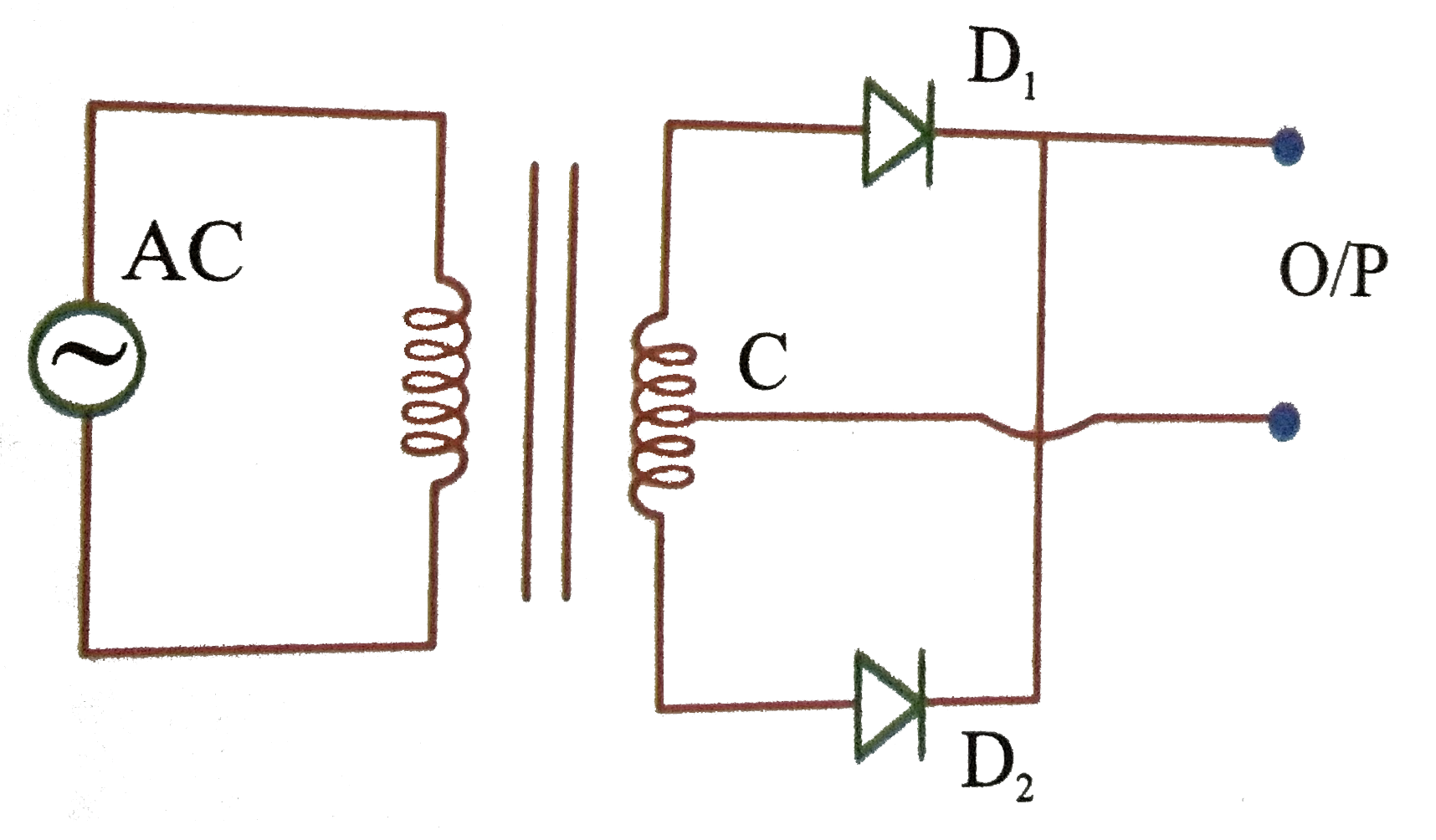 .
.
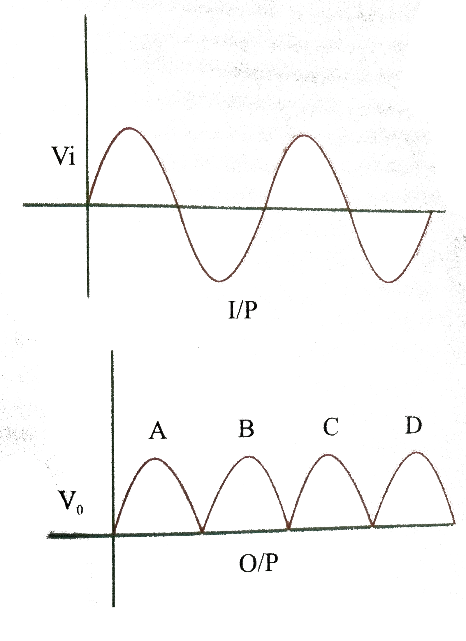 ACBA,CCB,DDA,B.C,D
P-N junction diode as rectifier (Half and Full wave)
View SolutionA full wave rectifier uses two diodes with a load resistance of 100Ω. Each diode is having negligible forward resistance. Find the efficiency of this wave rectifier.
View SolutionA full wave rectifier circuit along with the output is shown in the following diagram. The contribution(s) from the diode (1) is (are) -
View SolutionA full-wave rectifier circuit is operating at n Hz mains frequency . The fundamental frequency in the ripple would be
View SolutionIn a full wave rectifier circuit operating from 50Hz mains frequency , the fundamental frequency in the ripple would be
View Solution

