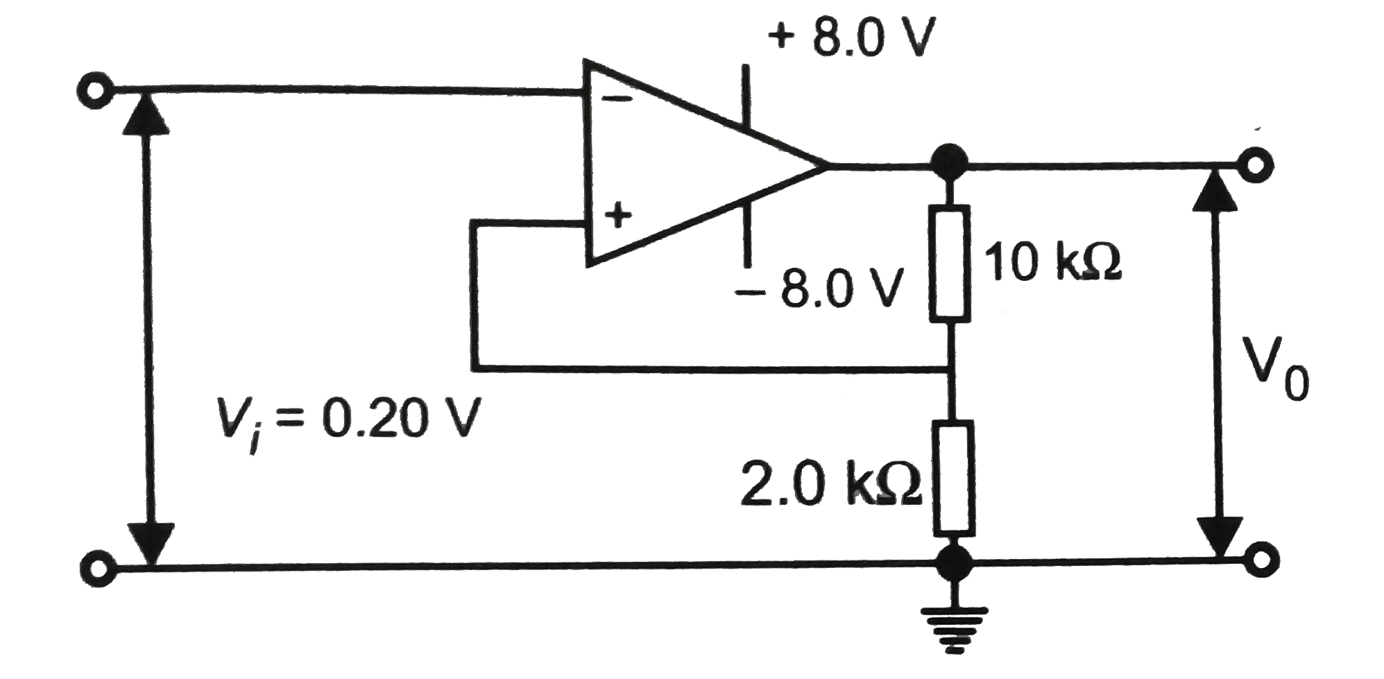
An input voltage Vi of 0.20V is applied to an operational amplifier connected as shown in the diagram. What is the output voltage V0?
0.20V
1.2V
0.80V
8.0V
The correct Answer is:B
The circuit configuration is a non-in-venting amplifier. The gain of the amlifier is given by the equation gain =V0V1=1+R1R2=1+102=6
thus, the output voltage V0 is
V0=6Vi=6(0.20)=1.2V
Topper's Solved these Questions
- SEMICONDUCTOR ELECTRONICSBOOK - A2ZCHAPTER - SEMICONDUCTOR ELECTRONICSEXERCISE - Section B - Assertion Reasoning
22 Videos
- SEMICONDUCTOR ELECTRONICSBOOK - A2ZCHAPTER - SEMICONDUCTOR ELECTRONICSEXERCISE - AIPMT/NEET Questions
77 Videos
- SEMICONDUCTOR ELECTRONICSBOOK - A2ZCHAPTER - SEMICONDUCTOR ELECTRONICSEXERCISE - Digital Electronics
40 Videos
- NUCLEAR PHYSICSBOOK - A2ZCHAPTER - NUCLEAR PHYSICSEXERCISE - Section D - Chapter End Test
29 Videos
- SOURCE AND EFFECT OF MAGNETIC FIELDBOOK - A2ZCHAPTER - SOURCE AND EFFECT OF MAGNETIC FIELDEXERCISE - Section D - Chapter End Test
30 Videos
Similar Questions
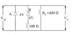
Two Zener diodes (A and B ) having breakdown voltage of 6 V and 4 V respecitvely , are connected as shown in the circuit below . The output voltage V0 variation with input voltage linearly increasing with time is given by :
(Vimput=0Vatt=0) ( figure are qualitative )
View SolutionPrimary of a transformer is connected to .5 V dry cell. What will be the output voltage?
View Solution
Knowledge Check
In the circuit shown in figure the maximum output voltage V0 is
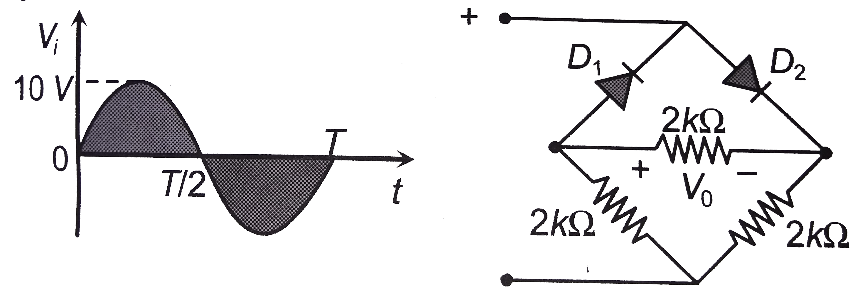 A0VB5VC10VD5√2V
A step voltage V0 is applied to a series combination of R and C as shown Fig. Then
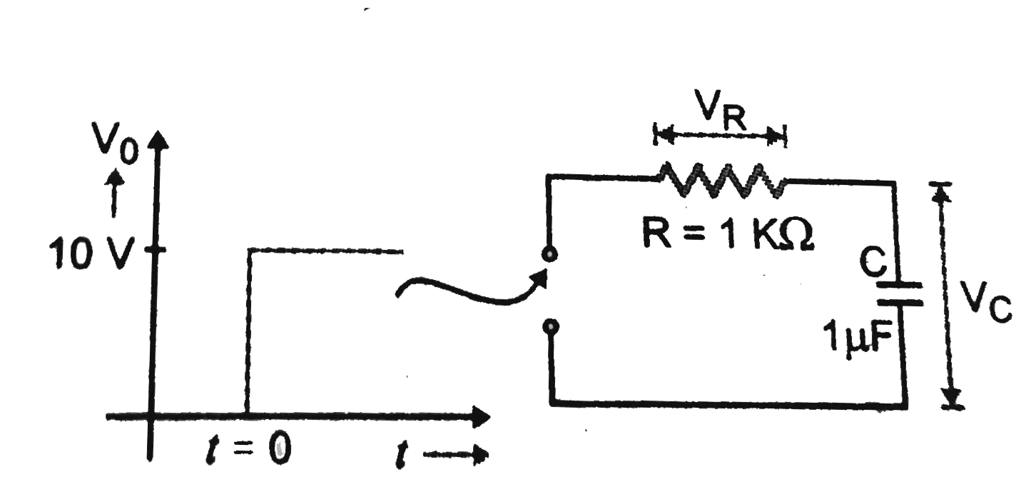 Aafter sufficienty long time VR=0Bas time passes, VR decreases as (1/t)Cafter 1ms,VC=6.3 volt (approximately)Dinitially, current through R is 10mA.
A small signal voltage V(t)=V0sinωt is applied across an ideal capacitor C:
ACurrent l(t) leads voltage V(t) by 180∘BCurrent l(t) lags voltage V(t) by 90∘COver a full cycle the capacitor C does not consume any energy from the voltage sourceDCurrent l(t) is in phase with voltage V(t)
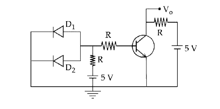
A circuit is arranged as shown in figure. The output voltage V0 is equal to ____________V.
View SolutionAn amplifier is represented by the circuit shown in Fig. Here ri is the input resistance of the amplifier and the voltage Vi is appearing across it. This voltage is amplified by a factor AV and appears across the load as voltage V0
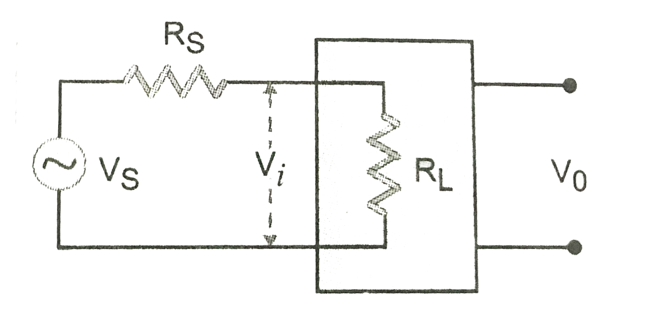
An external voltage Vs is applied at the input terminals of the amplifier via series resistance RS. What will be the apparent gain AV(=V0/Vs) of the ampilifier in terms of AV,RS and ri.
View SolutionThe figure below shows a circuit and its input voltage vi as function of time t.
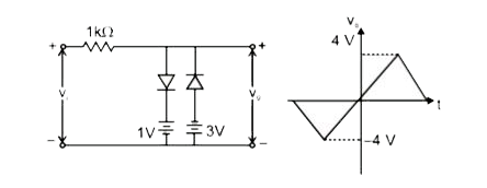
Assuming the diodes to be ideal, which of the following graphs depicts the output voltage v0 as function of time t ?
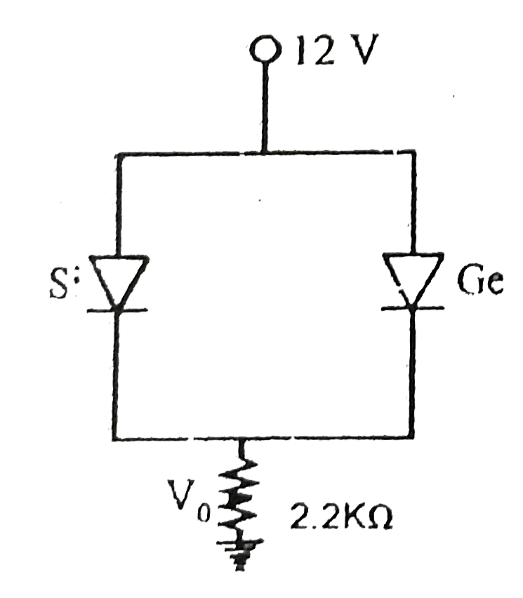
View SolutionIn the circuit shown in figure, Voltage V0 is
View Solution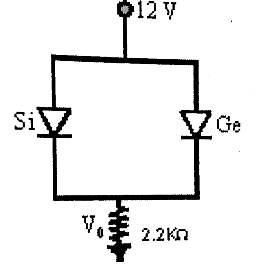
In the circuit shown infigure, voltage V0 is,
View Solution
