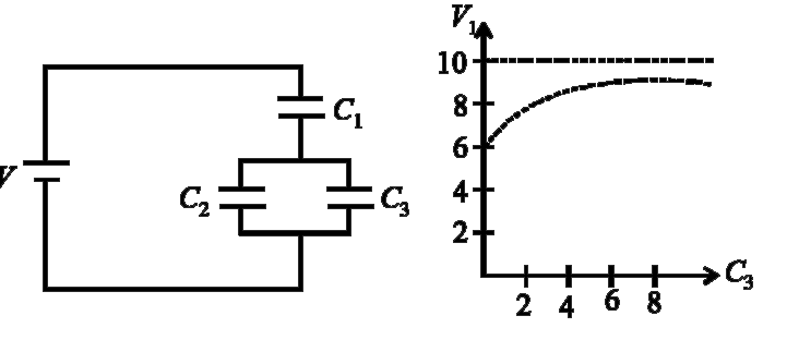
Capacitor C3 in the circuit is variable capacitor (its capacitance can be varied). Graph is plotted between potential difference V1 (across capacitor C1) versus C3.
Electric potential V1 approaches on asymptote of 10 volts as C3→∞
The value of C3 for which potential difference across C1 will become 8V, is
1.5C1
2.5C1
3.5C1
4.5C1
The correct Answer is:A
Step by step video & image solution for Capacitor C_(3) in the circuit is variable capacitor (its capacitance can be varied). Graph is plotted between potential difference V_(1) (across capacitor C_(1)) versus C_(3). Electric potential V_(1) approaches on asymptote of 10 volts as C_(3) to infty The value of C3 for which potential difference across C_(1) will become 8V, is by Physics experts to help you in doubts & scoring excellent marks in Class 11 exams.
Updated on:21/07/2023Topper's Solved these Questions
- ELECTROSTATICSBOOK - DC PANDEY ENGLISHCHAPTER - ELECTROSTATICSEXERCISE - Matrix Matching
2 Videos
- ELECTROSTATICSBOOK - DC PANDEY ENGLISHCHAPTER - ELECTROSTATICSEXERCISE - Integer
17 Videos
- ELECTROSTATICSBOOK - DC PANDEY ENGLISHCHAPTER - ELECTROSTATICSEXERCISE - JEE Advanced
44 Videos
- ELASTICITYBOOK - DC PANDEY ENGLISHCHAPTER - ELASTICITYEXERCISE - Medical entrances s gallery
21 Videos
- EXPERIMENTSBOOK - DC PANDEY ENGLISHCHAPTER - EXPERIMENTSEXERCISE - Subjective
15 Videos
Similar Questions
Capacitor C3 in the circuit is a veriable capacitor (its capacitance can be varied). Group is plotted between potential difference V1 (across capacitor C1) versus C3. Electric potential V1 approaches to 10 V as C3→∞. Given that C1+C2=10μF

EMF of the battery is equal to
View SolutionCapacitor C3 in the circuit is a variable capacitor (its capacitance can be varied). Graph is plotted between potential difference V1 (across capacitor C1) versus C3. Electric potential V1 approaches to 10 V as C3→∞. Given that C1+C2=10μF

The capacitance of the capacitor C1 value
View Solution
Knowledge Check
A capacitor or capacitance C1 is charge to a potential V and then connected in parallel to an uncharged capacitor of capacitance C2. The fianl potential difference across each capacitor will be
AC1VC1+C2BC2VC1+C2C1+C2C1D1−C2C1
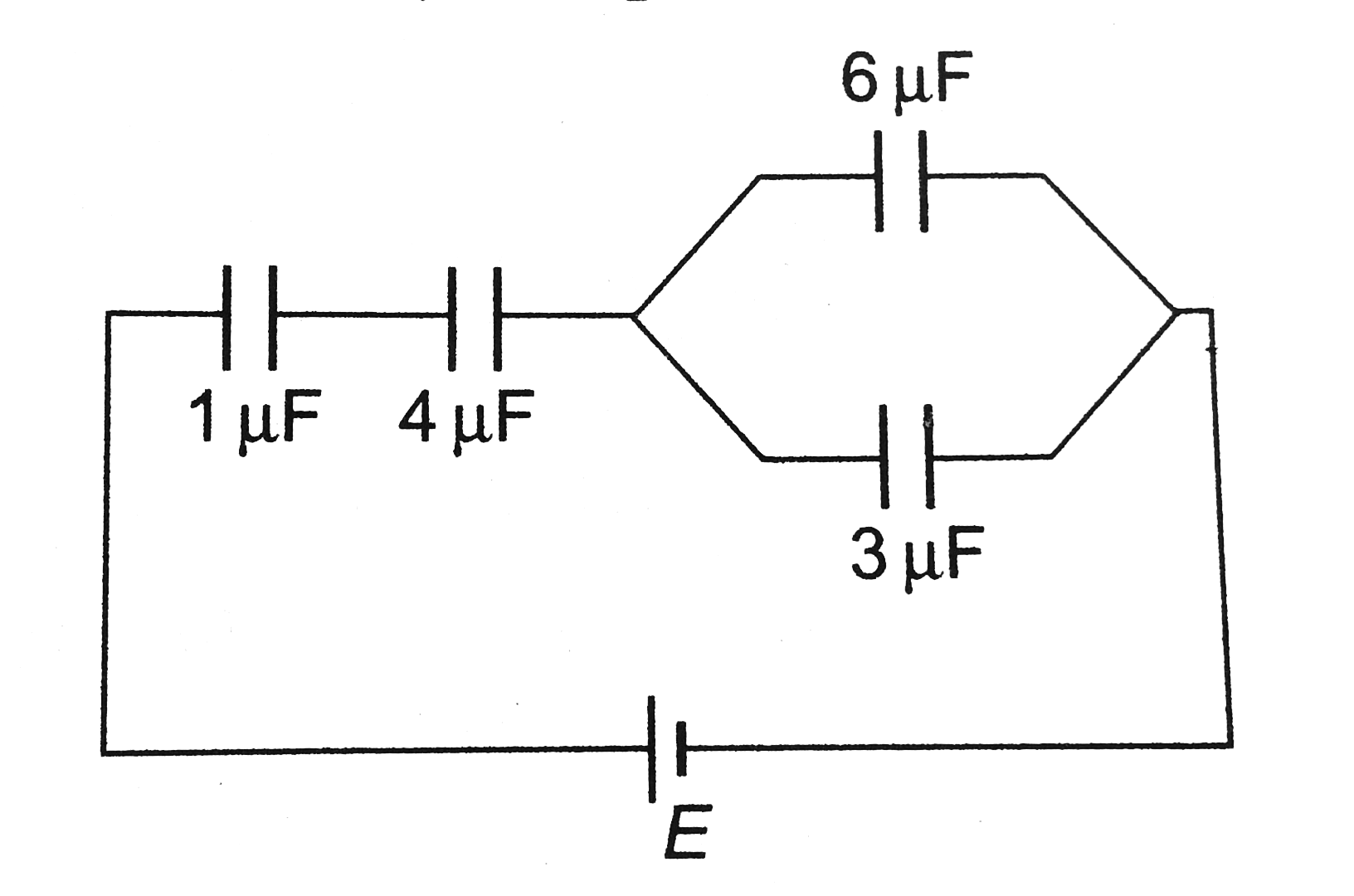
given that potential differene across 1μF capacitor is 10V. Then,

View SolutionIn the circuit shown in figure find

a. the equivalent capacitance
b. the charge stored in each capacitor and
c. the potential difference across each capacitor.
View SolutionTwo capacitors of capacitance 6µF and 4 µF are put in series across a 120 V battery. What is the potential difference across the 4 µF capacitor. (a) 72 V (b) 60 V (c) 48 V (d) zero
View SolutionTwo capacitors of capacitance 6µF and 4 µF are put in series across a 120 V battery. What is the potential difference across the 4 µF capacitor. (a) 72 V (b) 60 V (c) 48 V (d) zero
View SolutionThe 500μF capacitor is charged at a steady rate of 100μC/s. The potential difference across the capacitor will be 10 V after an interval of
View SolutionThe 500μF capacitor is charged at a steady rate of 100μC/s. The potential difference across the capacitor will be 10 V after an interval of
View SolutionTwo capacitances of capacity C1and C2 are connected in series and potential difference V is applied across it. Then the potential difference across C1 will be
View Solution
