Draw the circuit diagram of an illuminated photodiode in reverse bias? How is photodiode used to measure light intensity?
Video Solution
|
Answer
Step by step video & image solution for Draw the circuit diagram of an illuminated photodiode in reverse bias? How is photodiode used to measure light intensity? by Physics experts to help you in doubts & scoring excellent marks in Class 12 exams.
Updated on:21/07/2023Topper's Solved these Questions
- ELECTRONIC DEVICESBOOK - PRADEEPCHAPTER - ELECTRONIC DEVICESEXERCISE - LONG QUESTION ANSWER
2 Videos
- ELECTRONIC DEVICESBOOK - PRADEEPCHAPTER - ELECTRONIC DEVICESEXERCISE - PROBLEMS FOR PRACTICE
7 Videos
- ELECTRONIC DEVICESBOOK - PRADEEPCHAPTER - ELECTRONIC DEVICESEXERCISE - HIGHER ORDER THINKING SKILLS
1 Videos
- ELECTROMAGNETIC WAVESBOOK - PRADEEPCHAPTER - ELECTROMAGNETIC WAVESEXERCISE - II Focus multiple choice question
5 Videos
- ELECTROSTATICSBOOK - PRADEEPCHAPTER - ELECTROSTATICSEXERCISE - ASSERTION-REASON TYPE QUESTIONS
2 Videos
Similar Questions
Knowledge Check
Phot diodes are preferable used in reverse bias conditions for measuring light intensity because
ACurrent in reverse biase is less which is easier to measure compared to higher currents in forward biasBHigh fractional change due to photo effects in minority carrier dominated reverse bias current is more easily measurable than the high ractional change in the forward bias currentCLow fractional change due to photo-effect in minority carries dominated reverse bias current is more easily measurable than the high fractional change in the forward bias currentDCurrent in zero in reverse bias set-upStatement-I : A p-n junction with reverse bias can be used as a photodiode to measure light intensity.
Statement-II : In a reverse bias condition the current in small but it is more sensitive to changes in incident light intensity.AStatetment-I is True, Statement-II is True , Statement-II is a correct explanation for Statement-IBStatement-I is True, Statement-II is True , Statement-II is NOT a correct explanation for Statement-ICStatement-I is True, Statement-II is FalseDStatement-I is False, Statement-II is True
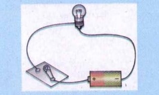
Draw the circuit diagram to represent the circuit shown below.

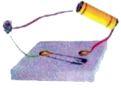
View SolutionDraw the circuit diagram to represent the circuit shown infigure.

View SolutionDraw the circuit diagram of a metre bridge to explain how it is based on Wheatstone bridge.
View SolutionWhy are photodiodes used preferably in reverse bias condition?
View SolutionDraw a p-n junction with reverse bias
View SolutionAssertion : Photodiode current work in reverse bias.
Reason : Change in diode increases with increase in intensity .
View Solution
