In the circuit shown in figure :
R=10Ω,L=√310H,R2=20Ω and C=√32mF. Current in L−R1 circuit is I1 in C−R1 circuit is I2 and the main current is I
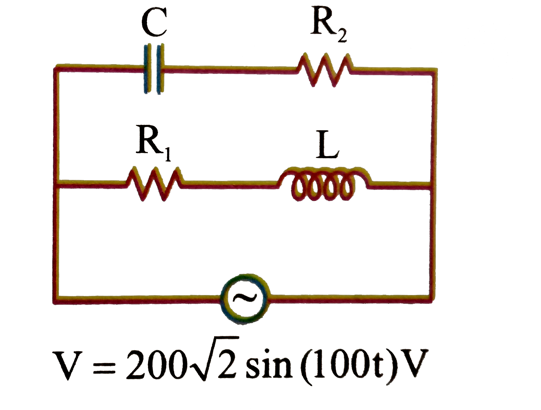
Phase difference between I1 and I2 is
20A
10√2A
20√2A
25A
The correct Answer is:B
Step by step video & image solution for In the circuit shown in figure : R = 10 Omega , L = (sqrt(3))/(10) H, R_(2) = 20 Omega and C = (sqrt(3))/(2) mF. Current in L - R_(1) circuit is I_(1) in C - R_(1) circuit is I_(2) and the main current is I Phase difference between I_(1) and I_(2) is by Physics experts to help you in doubts & scoring excellent marks in Class 12 exams.
Similar Questions
In the circuit shown in figure :
R=10Ω,L=√310H,R2=20Ω and C=√32mF. Current in L−R1 circuit is I1 in C−R1 circuit is I2 and the main current is I
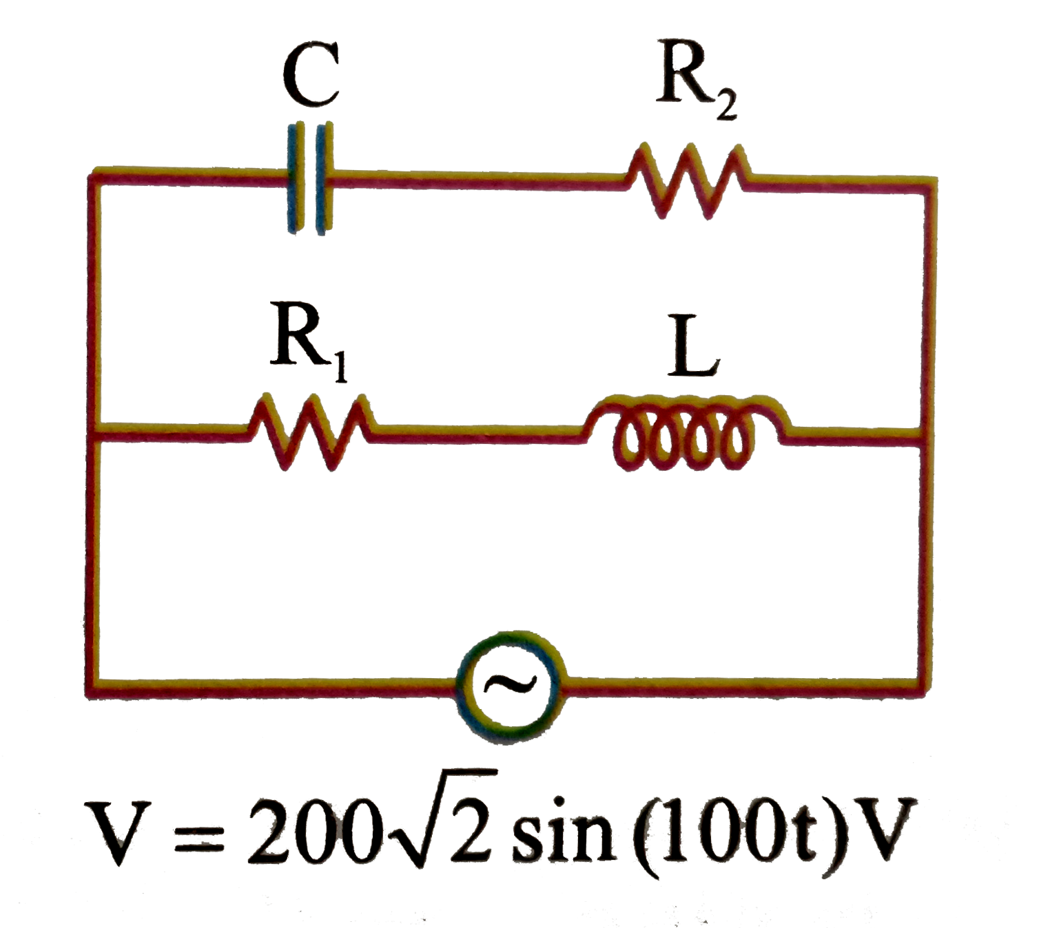
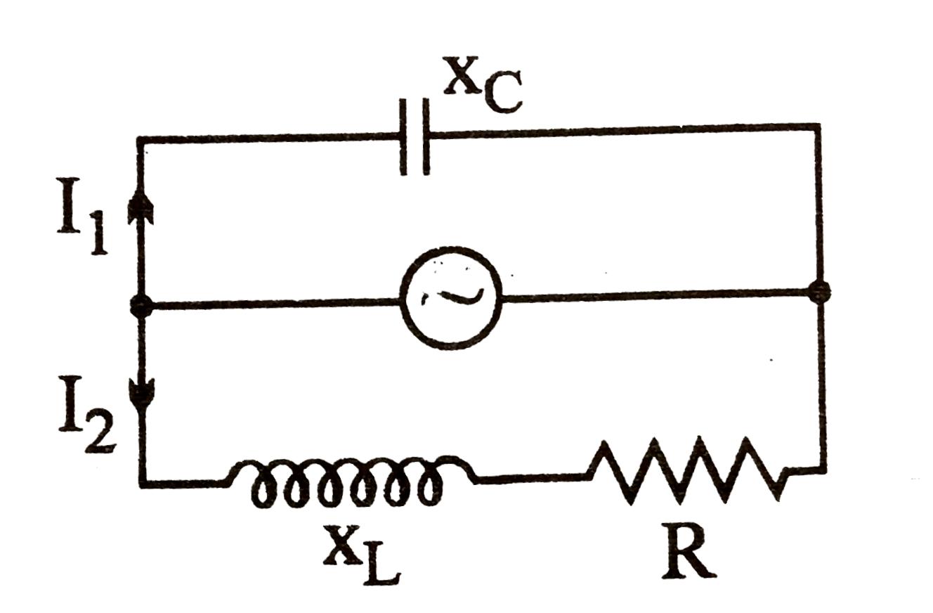
At some instant current in L−R1 circuit is 10A. At the same instant current in C−R2 branch will beView SolutionIn the shown AC circuit phase different between current I1 and I2 is
 View Solution
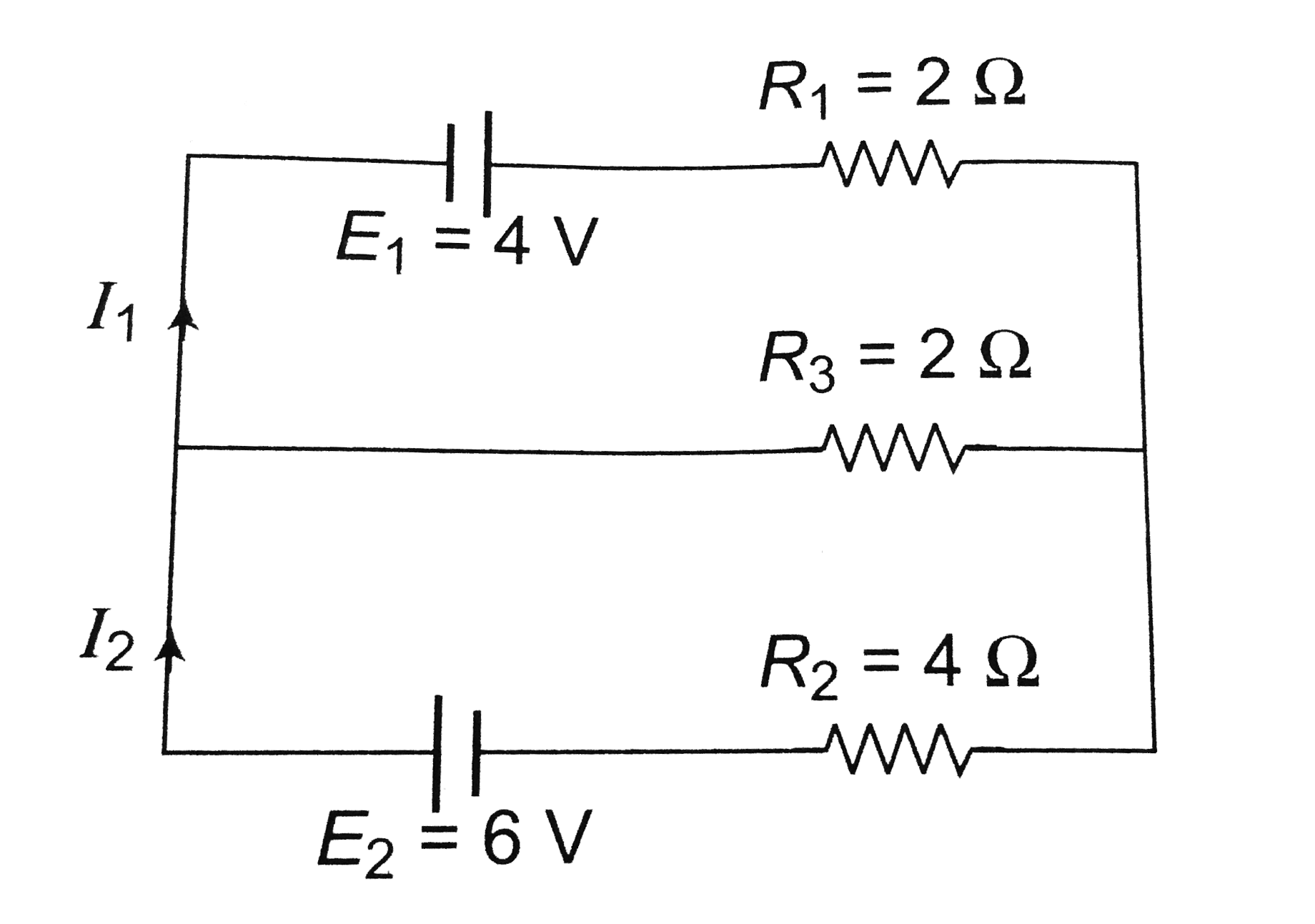
In the circuit shown below E1=4.0V,R1=2Ω,E2=6.0V,R2=4Ω and R3=2Ω. The current I1 is
 View Solution
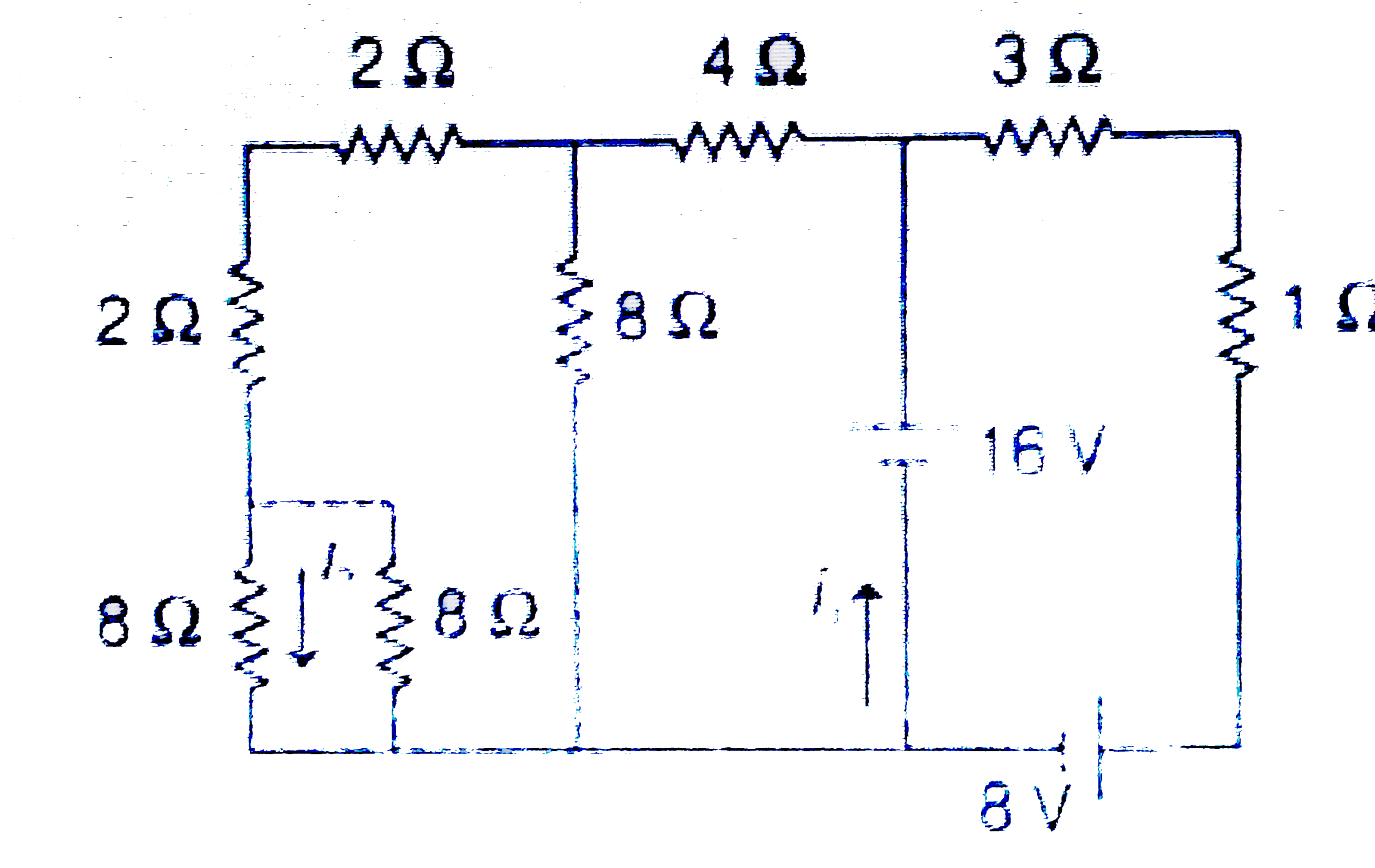
In the circuit shown in figure ,find the ratio of currents i1/i2.
 View Solution
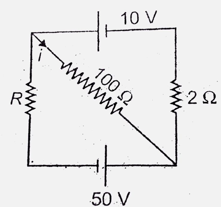
In the circuit shown, the current I will be zero when R is
 View Solution
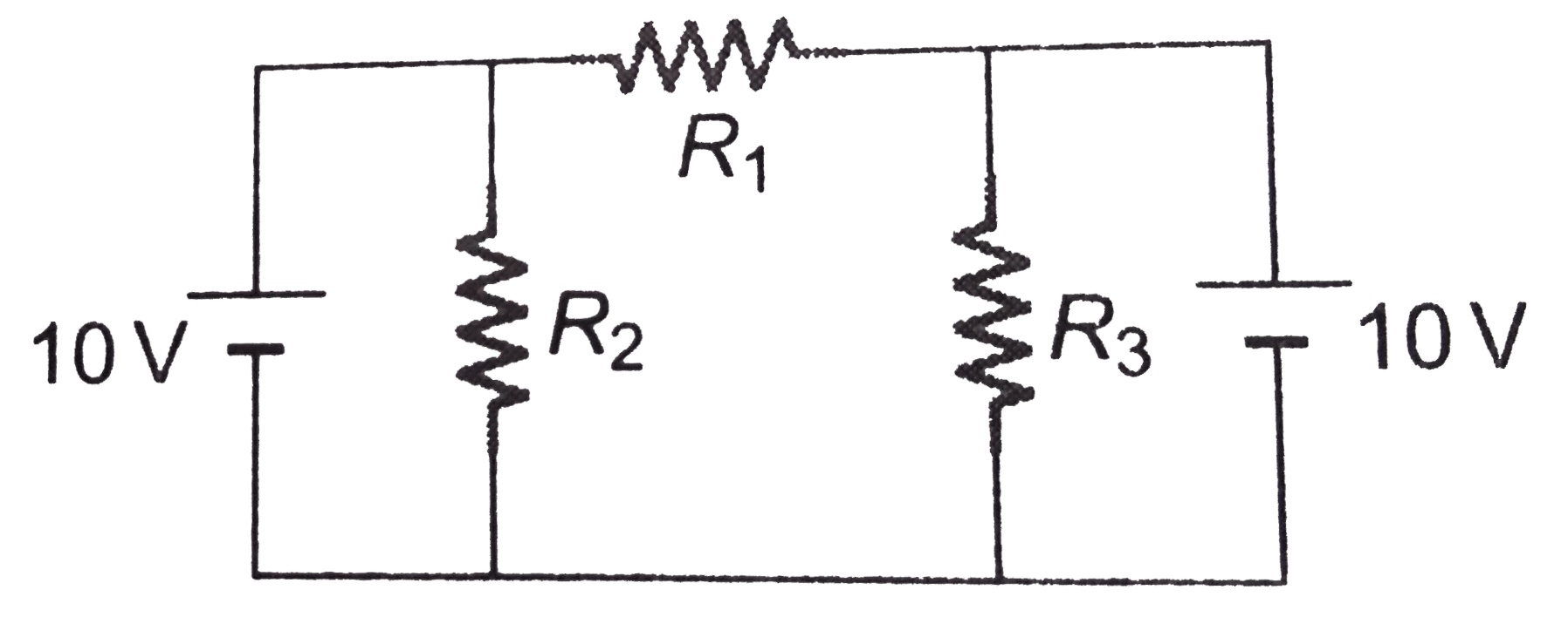
In the curcuit shown in figure R1=R2=R3=10Ω. Find the currents through R1 and R2
 View Solution
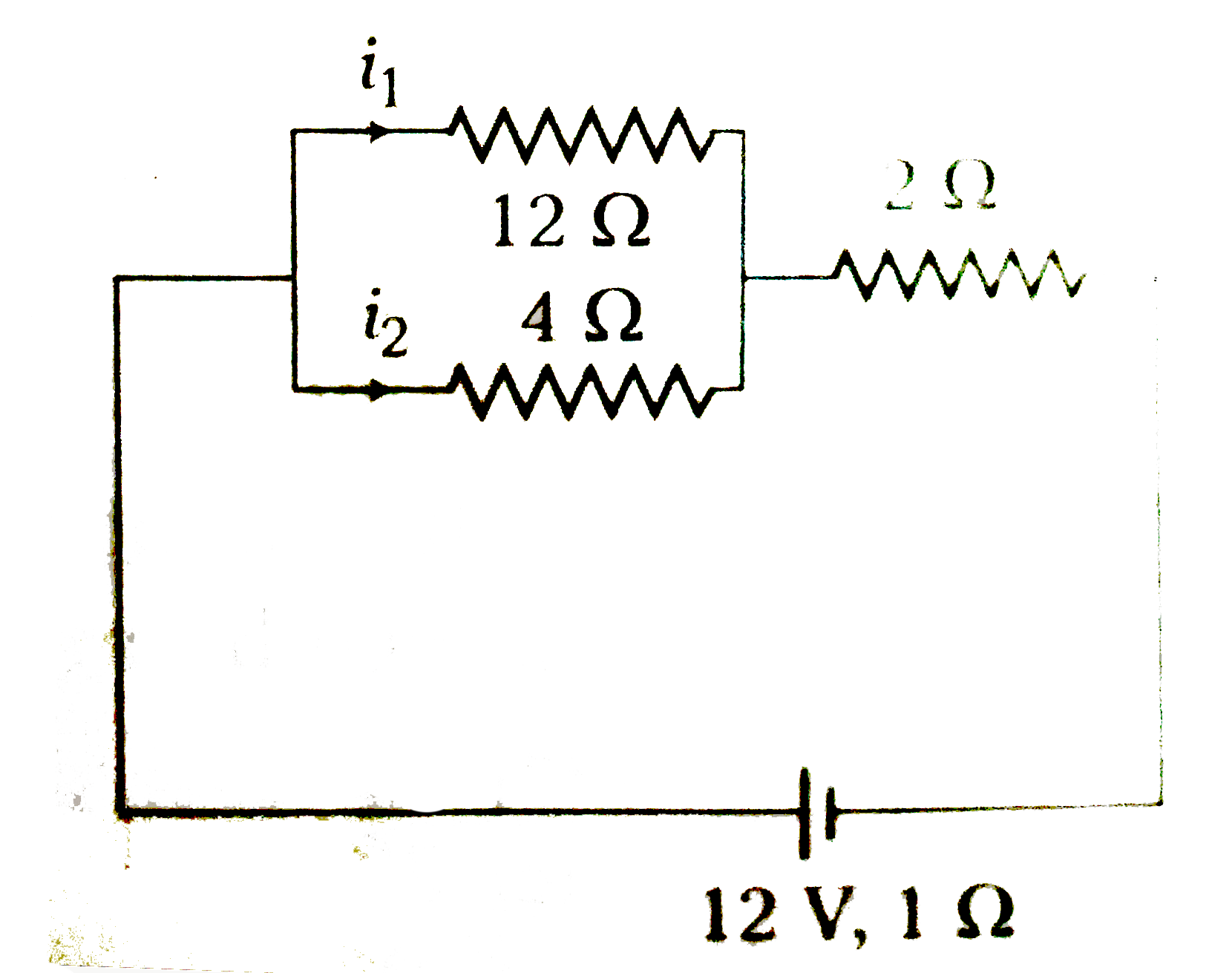
In the circuit shown, the currents i1 and i2 are
 View Solution
In the circuit as shown in figure, the ratio of current i1/i2 is
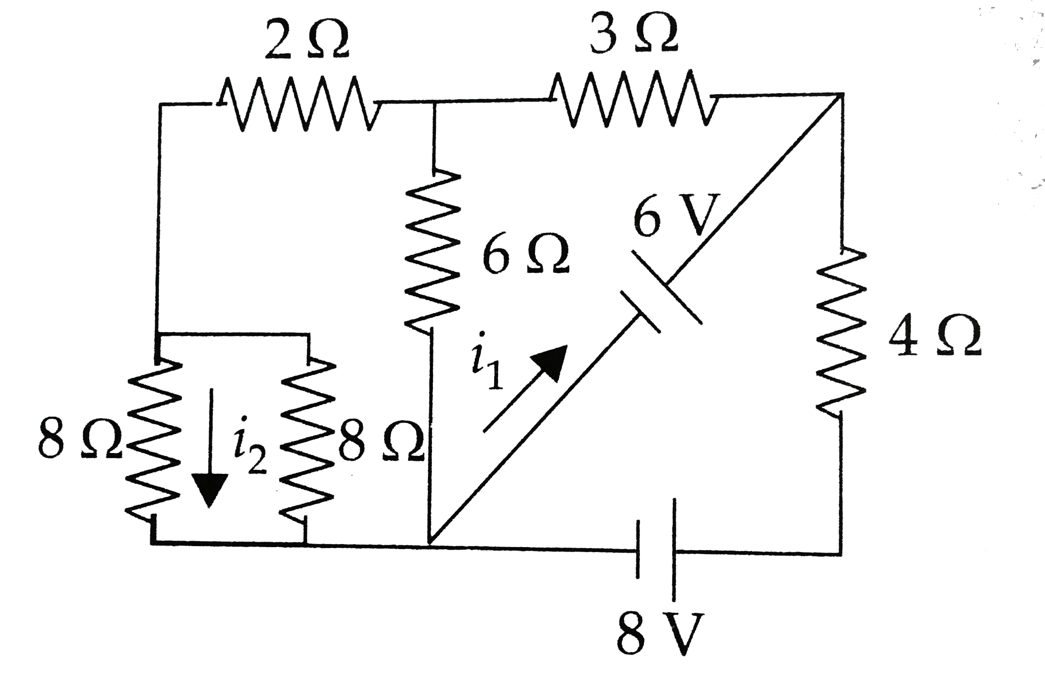 View Solution
In the circuit shown in figure, R(1)=1Ω,R2=2Ω,C1=1μF,C2=2μF and E=6V. Calculate charge on each capacitor in steady state
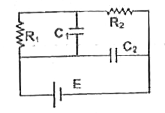 View Solution
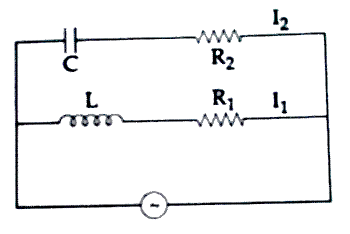
In the value circuit, C=√32μF,R2=20Ω,L=√310H, and R1=10Ω .Current in L−R1 path is I1 and in C−R2 path it is I2. The voltage of A.C source is given by, V=200√2sin(100t) volts. The phase difference between I2 and I1 is :View Solution

